
Home
Dust Collection Basics
Equipment
Ducting & Hoods
Wood Toxicity Table
Testing
FAQs
Projects
Administrative
Financial Help
Contact & Email

Dust Level Sensor
-
Challenge
I make a lot of wood dust, love your cyclone that works incredibly well compared to my first two cyclones, but keep having problems with filling the filters full of dust because I forget to empty the dust bin. What do you recommend to help me know when to empty the bin? What do you use? - Jeff
Jeff, this gets asked often and is an important question. No matter how efficiently a cyclone separates off the dust, as soon as the dust bin gets full everything goes right through the cyclone into the filters. Because most small shop owners use far less than the monster horsepower blowers used in large commercial woodworking facilities, dirty filters quickly kill the airflow from our less powerful blowers that we need for good fine dust collection. Cleaning our expensive filters quickly wears them out opening the pores so they freely pass the finest unhealthiest dust right through. I tend to get overly involved in what I am doing and regularly forget to empty the dust bin, especially when making lots of dust. As a result, cleaning my filters continues to be an ongoing problem. I installed a sealed clear polycarbonate window in my dust bin so I can see when it is getting full. The theory was good but it works poorly. The chips flying around inside the bin rubbing on that plastic creates a static charge. That static charge attracts a thick coat of fine dust that covers the window. Wiping that plastic with clothes drier fabric softener sheets helps some, but not enough. The same goes for my later efforts to add electronic sensors to my bin. My weight triggered approach and also my photo cell approach failed badly. The weight triggered approach assumed the dust created is a fairly constant weight. It is not and the weight needed to tell me when my bin is full of light planer shavings is about one tenth that for a full bin of MDF dust. Likewise, the photocell technique that others also tried constantly gives off bad readings due to the sensor and light getting dirty or covered with a chip. In short, a full dust bin has remained an ongoing problem. The no longer available clear plastic cyclones solved this problem because they let us see when the dust is not dropping, unfortunately, we still have to look. That’s why I am sharing a better solution shared by Hajime Sugisawa. "Sugi" is a bright electronics fellow who wanted to give a little back after building my cyclone design. His English language skills are a little challenged, but infinitely better than my Japanese, so I am sharing his design.
Alternative 1: Since I published this design, others have shared a fix that actually makes a simple photocell solution viable. Instead of putting the light and sensor inside the dust bin, putting windows at the bottom of the pipe just before it connects to the top of the dust bin allows putting a small Christmas tree light on one side and standard 120V photocell used to control outdoor lights on the other. When the light is blocked that cell turns on an AC power source. You can have that power either ring a bell or have it activate a relay which cuts power to your motor switch. This works well, is cheap, requires no special parts, and turns off the cyclone blower motor when the bin fills just into the hose. There is enough scouring that the windows stay clean.
Alternative 2: I continue to play with many different things including robotics. If you want another more elegant inexpensive alternative consider using one of the inexpensive robotic microprocessor boards coupled to this Sharp distance sensor. Make sure you order the pigtail cable with it as the leads are difficult to solder onto. - Request
I am sharing this information as a service only. Please do not email me with electronic questions. I burned out on digital design as a career back in the early seventies after building my first computer from scratch and teaching college digital electronic design classes for years. This is one of the fastest changing areas ever. My range of activities and limited time left me struggling to keep up and eventually saying enough. I have no interest in getting back into digital electronics and again becoming current. Although I am happy to accept advice, safety, and improvement suggestions, I really do not want to field electronic questions because my interest is too little and knowledge too dated. Likewise, I long ago learned that recommending part suppliers is a never ending maintenance chore, so I am sharing Sugi’s links and a link to All Electronics that I have long used as a source for my own parts. I am not going to maintain these links nor going to take responsibility for looking at or blessing other alternatives. A number of people have build these sensors successfully, but a few have provided some feedback that this design can be improved with a few changes. I've included some feedback from Doug who worked through some problems when building this unit. Finally, any time you work with electricity and fine dust, there are potential hazards. Please read my below disclaimer and either know what you are doing or get competent help to ensure what you build is safe.
- Summary
This simple sensor costs about $20 to build and works well. It shows a light when working and when the dust bin gets full that light goes out and a buzzer sounds. This detector is built from a solar motor, 12 volt DC transformer, and a few readily available electronic parts. The motor is mounted outside the dust bin with a small fan sitting inside. The fan stops turning when the dust level gets near the top of the bin and blocks fan rotation. Sugi’s circuit senses when the fan stops turning and turns off the bright light emitting diode (LED) light and turns on the buzzer. Because the current is so small, this approach will not harm the motor when it is blocked nor does it pose a fire danger. This circuit buzzes on startup for a few seconds while the solar motor fan comes up to speed letting us know the circuit works. A switch to the buzzer can easily be added or the buzzer left out of the circuit if noise is a problem. That still leaves the LED turning off to show when the bin is full, but would not work for me as I need a strong buzzer to get my attention.
- Principle
The solar motor runs about 300-1000 RPM with 15-100mA current while most popular DC toy motors run at 5000 to 10000 RPM with 100-500mA. Unlike toy motors, the slower rotation and reduced current for the solar motor allows our dust to easily stop the impeller.
In this circuit, the solar motor is connected in serial to resistor R1 and current is limited about 20mA at a constant rotation. When the terminal voltage is about 1 volt, then Q1 is activated turning the LED light on and Q2 off, so the buzzer does not sound.But when the Impeller (motor) rotation is interrupted, the voltage falls down almost 0 volts. Q1 goes off turning off the LED and activating Q2 which sounds the buzzer letting us know it is time to empty the dust bin.
When starting the solar motor needs extra current which is why C1 is included in the circuit. - Fig.1A Parts List
This is the original circuit, but Sugi had reports that this shematic doesn't work correctly if the motor voltage is higher than Q1 threshhold (about 0.6V) at the time the force is stopped. So, he made some modifications to correct this that also makes adustment easier. (See Below)
Figure.1APart Discription EQV US Part Vendor Solar Motor H-151Solartek #700-60062-00 http://store.sundancesolar.com Impeller Plastic 60mm dia. Note1 Q1 2SC1815 2SC1775A www.allelectronics.com Q2 2SC1815 2SC1775A same above D1 1S1558 IN4002 same above LED Unknown spec. LED-120 same above Buzzer 12V DC SBZ-100 same above C1 470uF 25V 470uF 25V same above R1 600 ohm Note2 R2 10Kohm 1/4W 10Kohm 1/4W same above Note3 R3 1Kohm 1/4W 1Kohm 1/4W same above Note3 R4 10Kohm 1/4W 10Kohm 1/4W same above Note3
note1 If you don't find simular one,You can make it yourself note2 Get this value by pararell connection of multiple resistors note3 Typically sold 10 pieces minimum - Fig2B Parts List
This circuit adds LM393 which provides a couple of voltage comparaters that detect a slight volatage difference. VR1 is the aduster of the reference voltage.

Figure.2BPart Discription EQV US Part Vendor Solar Motor H-151Solartek #700-60062-00 http://store.sundancesolar.com Impeller Plastic 60mm dia. Note1 U1 LM393 LM393 www.allelectronics.com Q1 2SC1815 2SC1775A same as above D1 1S1558 IN4002 same as above LED1 Unknown spec. LED-2 same as above LED2 Unknown spec. LED-1 same as above Buzzer 12V DC SBZ-100 same as above C1 470uF 25V 470uF 25V same as above R1 600 ohm Note2 R2 10Kohm 1/4W 10Kohm 1/4W same as above Note3 R3 10Kohm 1/4W 10Kohm 1/4W same as above Note3 R4 10Kohm 1/4W 10Kohm 1/4W same as above Note3 R5 1Kohm 1/4W 1Kohm 1/4W same as above Note3 R6 1Kohm 1/4W 1Kohm 1/4W same as above Note3 VR1 2Kohm trimpot 2Kohm trimPot same as above Note4
note1 If you don't find simular one,You can make it yourself note2 Get this value by pararell connection of multiple resistors note3 Typically sold 10 pieces minimum() note4 You can use both linear pot and trimmer pot(potention meter) LPT-2.5K looks available. - Construction
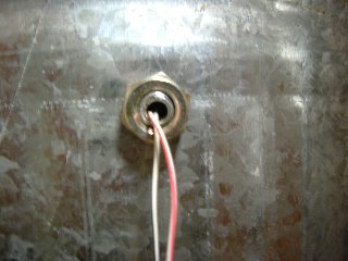
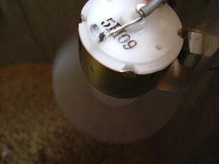
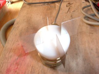
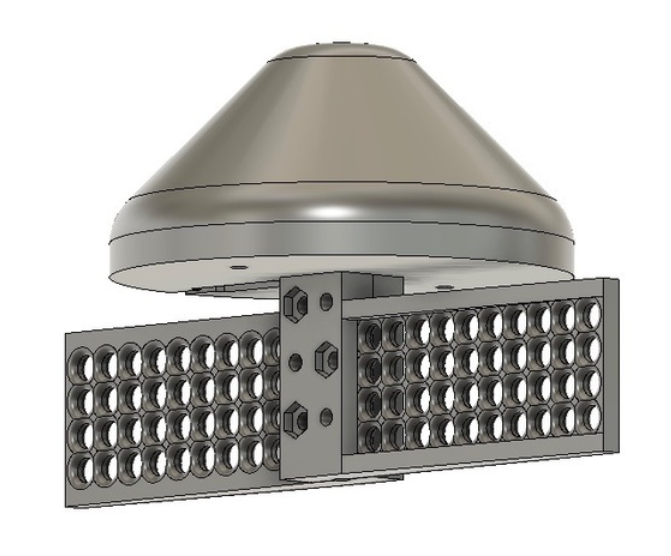
Make some holes on a piece of aluminum angle to support the solar motor and holding screw .I drilled through to hold an 8mm hex bolt and secured the motor cable as pictured. Then unit is secured with this 8mm bolt and nuts on either the top or side of dust can.
 @
@
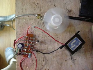
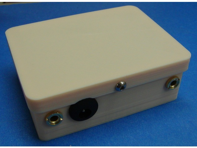
This simple circuit easily was built on a lag terminal strip by soldering without need for a printed circuit board. R1 is an assembly of multiple resistors. See Fig.2. Resistors here are sold in 10 piece minimum lots, so this made good use of having to buy so many.
- Testing
After finishing construction, check all connections then connect the 12V DC adaptor. Buzzer sounds for a few seconds as the motor starts and gradually comes up to full rotation speed. When at full speed the buzzer should stop and the LED turns on.
Try stopping the impeller with your finger. If it blows too hard or seems to move too fast, remove one 10K ohm resistor from R1 assembly. If the motor rotational speed is not constant, add one more 10K ohm resistor to R1 assembly. When the rotation stops the LED should turn off and the buzzer sounds.
If the motor does not start again when you remove your finger, disconnect and then reconnect the DC adaptor.
I keep this sensor running while I'm in my shop. - IMPORTANT Notes!
-
I made this circuit with parts available in Japan, you may have to use other parts and it might take a little adjustment to work with a different parts configuration. This is especially true if you use a different fan because the detection sensitivity depends on the radius and the shape of fan impeller (propeller).
-
If the impeller rotation sucks up dust, reverse the motor connection so that impeller blows the other direction.
-
If you don't like buzzer noise, either put a switch in front of the buzzer or remove R4, Q2 and buzzer. You then will only have the LED for your indicator. (Bill’s note: You also could replace the buzzer with some bright automotive flashing LEDs.)
-
To keep the impeller from being damaged by larger debris, you should surround it with a wire guard.
-
-
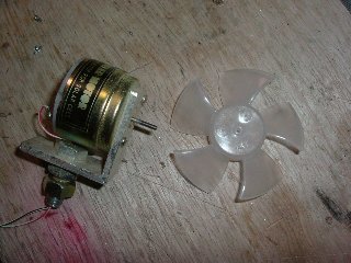
Making Your Own Impeller - I made four small blades with aluminum sheet (0.3mm thick, 20*30 mm wide) and mounted them on a small plastic rod that was about 30 mm in diameter and 10 mm thick. (Bill’s note: You also could make two longer blades, cut opposing slots, and slide them together to keep from having to worry about the blades flying loose from their mounting.)
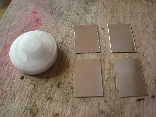
I then made a 2.0 mm diameter through hole at the exact center for a tight fit on the motor shaft followed by cutting four slits with an XACTO saw (the blade thickness 0.27 mm) to hold the impeller blades.
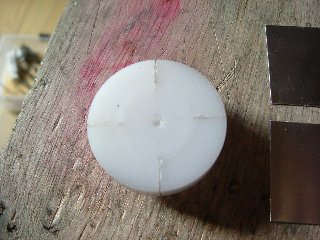

Insert blades into slits. If they feel loose, use adhesive (for metal and plastic).
I don't know this shape is best or not, but after adjusting a little because it is heavier and draws a little more current, it works just fine.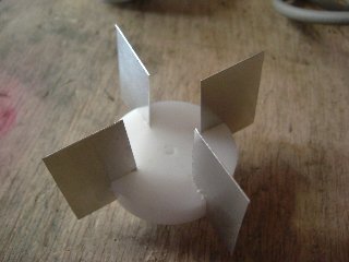
Now that should allow you to build a pretty incredible dust bin sensor for under $20.
- Feedback
I just got done building the dust bin sensor. I discovered that the schematic is incorrect. If you wire it as it is on your site, it will work just the opposite as one would want i.e. when the motor is running, the red light is lit and the buzzer sounds and when the motor is stalled, the buzzer is silenced. I checked with a ham friend of mine and we put our heads together and found that if you switch wiring to pins 2 and 3 of the IC, that it works correctly. I also found that with the circuit as wired, that the buzzer will give a high pitched noise when the motor is running, I found that if I connected three diodes in series on the 12 volt side of the buzzer, that the soft ringing could be eliminated. It reduces the voltage to the buzzer enough to get rid of that resting whine. It likely also reduces the voltage to the buzzer when it is summoned to work (when the motor is stalled) and so also reduces the total volume of the buzzer when it is supposed to alarm. I haven't hooked it up to the cyclone dust bin yet, so I don't know if it will be too quiet to hear (however according to all the complaints from my wife while I was testing it, it should be OK. HaHa)
I also discovered that the supply voltage is quite critical. When I used a "12 volt" "wall wart" supply (which actually produces 16 volts) it didn't work (couldn't quiet it down).
I ended up using a "9 volt" supply (which actually produced 12 volts and it worked just fine.
Just thought I would provide you with what I experienced.
Doug
I worked with Sugi and did find one problem, but now all the above diagrams are fixed and work properly.
bill
- Another Alternative
Jon Mackey is a fellow woodworker who like me enjoys tinkering with electronics. He needed help knowing when his dust collection bin was full. He checked into the photo based sensors and decided they just did not make sense as there was too much chance of either the light or photocell getting blocked and needing constant cleaning. He also looked at weight and pressure sensors and realized wood dust weight is too inconsistent depending on the type of wood and machining process. He researched how the large professional firms sense a bin full condition and realized he could build something similar that was both simple and affordable. He used an Arduino processor, small motor and tiny circuit board with a simple program as the smarts behind his sensor. If you would like to learn more take a look at what he shared at his Dust Collector Bin Full Sensor site. Additionally, Jon came up with a sensor and alarm to let him loudly know when the bin was full at Bin Sensor Alarm site.
- Diclaimer