

Home
Dust Collection Basics
Equipment
Ducting & Hoods
Wood Toxicity Table
Testing
FAQs
Projects
Administrative
Financial Help
Contact & Email

Ducting
- Disclaimer
- Ducting Introduction
- Basics
- Dust Volumes
- Existing Dust Collection
- Dust Collection Standards
- Resistance
- Ducting Diameter
- Leaks
- Airflow Requirements
- Power Requirements
- Layout & Ducting Design
- Ducting Components
- Tool Ducting
- Static Electricity
- Noise Control
- PVC Confusion
- Frequently Asked Ducting Questions (FAQs)
- Disclaimer
Because improperly designed ducting can cause fires, fail to meet local codes, etc., these drawings, plans, procedures and words are for information only. USE THIS AT YOUR OWN RISK! HIRE A PROFESSIONAL ENGINEER to design, specify, test, and certify performance of any industrial dust collection system if you have a commercial or an industrial application, allergies, other medical problems, people working for you, a large shop, work with hazardous materials, or are subject to regulatory oversight. Neither I (Bill Pentz), American Air Filter, nor any other references or links on these pages will accept any liability for the applicability of this information to your specific situation or any damages or injury caused to people or property from the use of this information or from any associated links. No claims are expressed or implied as to the safety, usefulness, or accuracy of this information. Your actions are your responsibility - VERIFY and CHECK information out before proceeding, and don't attempt anything without the required skills.
- Ducting Introduction
This page translates the engineering ducting solutions that the experts who guarantee customer air quality use. If you have not already read at least the Home and Medical Risks pages, you should read those pages first to better understand fine dust risks and how poorly most do at providing good protection. The peer reviewed medical research is clear that every fine dust exposure causes a measurable loss of respiratory capacity, some of this loss becomes permanent, the larger and longer the exposure the greater the damage, and in spite of this damage from each exposure being small the damage builds over time to eventually cause asthma, COPD, emphysema and also worsens other age-related diseases often resulting in shortened life spans. The problems are many. Almost all small shop vacuums, dust collectors, cyclones and air cleaners miss collecting significant fine dust. Worse, most small shop vendors sell too open filters that freely pass the unhealthiest invisible fine dust and they also sell undersized filters which causes these filters to rapidly wear out and then freely pass the finest unhealthiest dust. OSHA testing shows that with every twenty pounds of sawdust we make enough fine dust to cause 15,119 typical two-car garage sized shops to fail an EPA air quality test. Fine dust lasts nearly forever unless it gets wet. Most vent our dust collection systems inside which allows the fugitive dust that escapes collection to build to dangerously high levels. Almost all hobbyists and six out of seven professional woodworkers work in small shops that are not government inspected or covered by any standards except what we choose to put in place for ourselves. Most home insurance inspectors, building inspectors and fire marshals will fail almost all small shop dust collection solutions due to serious safety concerns. Worse, government testing shows almost all even very clean looking small shops build up so much fine invisible dust that just walking around without any additional woodworking launches enough fine dust airborne to fail EPA air quality tests. The earlier pages on this site explain how to get good fine dust protection without having to install good fine dust collection. This page assumes you have already decided to move forward to good collection. Good collection requires ample airflow along with having the right hoods, tool ports, tool internal ducting, flex hoses, duct, wyes, blast gates and other components to support the level of dust collection we want. We need to follow the expert advice to ensure collecting the fine dust, transporting it for disposal, then getting rid of it.
- Basics
- Dust Volumes
As shared previously fine invisible dust is so unhealthy that the EPA sets very tough indoor air quality standards. Woodworking makes huge amounts of fine dust compared to how little it takes to exceed these standards and harm our health. On average with every twenty pounds of sawdust we also make enough fine invisible dust particles to cause 15,119 typical two car garage sized shops to fail an EPA air quality test. So, unless we use tools that totally enclose the dust making activities, when woodworking we need to worry about fine dust. Where this dust comes from is simple. At a microscopic level wood consists of dry very brittle tubes, so every time we work wood with blades, bits, cutters and sandpaper these tiny tubes explode into millions of fine invisible airborne dust particles. Just about every woodworking machine and hand tool operation launches fine dust particles airborne. A particle counter shows making a perfect long shaving with a razor-sharp hand plane that makes no visible dust launches millions of fine invisible particles airborne. These fine particles get by our natural protections then lodge deep in our respiratory tissues where they do damage and release toxic chemicals.
- Existing Dust Collection
Most existing small shop dust collection equipment works poorly because most small shop vendors do not follow industry standard practices to build dust collection systems. They provide undersized insufficient horsepower blowers, improperly sized ducting with poorly designed and made fittings, blast gates, and tool hoods. They also improperly locate our equipment, store sawdust to create a serious fire hazard, and generally use undersized far too open filters. This page addresses each of these problems. In addition to this equipment providing poor dust collection, almost all existing small shop dust collection equipment provides terrible fine dust collection. The makers of these tools don't understand the difference in the physics between sucking and blowing. We all know from using our shop vacuums on blow that blown air will hold together for many feet and blow stuff all over. We also know from using these same shop vacuums that the only way to pick up sawdust when sucking is to get our hose or attachment right next to what we want to suck up. The reason is sucked air comes from all directions at once, so airspeed falls off at roughly twelve times the distance squared. In simple words this means normal room air currents are moving faster than our sucked air so the fine dust gets blown all over. This helps explain why a system that can suck up a tape measure or heavy tool can't do a good job collecting the fine dust that we can move with the slightest breath. The problem is normal room air currents move faster than sucked air currents so will blow the fine dust all over.
- Dust Collection Standards
Fortunately, the better air engineering firms that sell dust collection equipment and guarantee customer air quality share what they found must be done to capture the fine dust before it can escape. Since we use the same size and types of tools as smaller commercial tools, most of what we need to do for good fine dust collection is already laid out in detail. They set minimum standards that those who install their systems must follow to ensure good fine dust collection. Many publish their information on the Internet such as Cincinnati Fan Engineering Data. They provide simple formulas and approaches to help design our ducting to move the needed air with ample volume and speed at each tool. They also share the air speeds measured in feet per minute (FPM) we need to pick up various materials including sawdust and chips. They also give the airspeed needed to keep these items entrained meaning airborne in our ducts. They share that we need the right sized ducting to carry each different airflow. They also provide equations to help us properly size our ducting. Ducting size is very important as too small limits the total air volume and too large lets the airspeed drop so low that the dust builds into large ducting piles. Wood dust piles in our ducts can reduce airflows and cause plugging, but the more serious danger is piles of wood dust in our ducts pose a serious fire hazard as any spark that goes into a pile can quickly get fanned into a dangerous fire. The most common problem with duct piles is when they break loose they slam down the duct hard enough to blow apart our ducting joints and go right through separators then destroy blower impellers, bearings and filters. These experts share how to avoid these piles. They found we need the same airspeed to pick up the chips as we do to keep them moving in vertical ducting runs. They also found because we are not working against gravity in horizontal ducting runs we can get by with a little less airspeed to keep the dust moving. They found we must maintain airspeed inside our vertical ducts of 3800 FPM to collect most sawdust and up to 4500 FPM for larger chips. That means we also need these same air speeds to keep the vertical runs from plugging. We need at least 2800 FPM to keep the horizontal runs clear. Most air engineers add a little safety factor so design their systems to provide at least 4000 FPM airspeed in the vertical runs and 3000 FPM in horizontal runs. If you need to pick up larger chips and small blocks you will need to step up to the 4500 FPM airspeed.
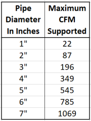
The experts also did considerable research which they have refined with decades of testing to work out how much air volume is needed at each size and type of tool to get good chip collection and get good fine dust collection. They found almost all small shop stationary tools get good collection of the same sawdust and chips we would otherwise sweep up with a broom with just 350 CFM of airflow. Fine dust particles are so small they are invisible without magnification. Fine dust particles are also so light they behave more like an odor so almost any air movement will blow the fine dust all over. They found to collect fine dust and overcome normal room air currents, we need to be pulling in the air at least 50 feet per minute out to a distance of just over fifteen inches all around the working areas of our tools. Clearly the larger the tool working area the greater the air volume required. Air speed and air volume are related with a simple formula FPM = CFM/Area where area is measured is square feet. With our knowing how far out we have to move this 50 FPM airspeed we can calculate the CFM meaning cubic feet per minute air volume. We end up calculating the surface area of a sphere with a radius of just over 15 inches, convert that to square feet then solve this formula and find most small shop tools need right at 1000 CFM airflow for good fine dust collection. This explains why it takes nearly three times more total air volume to get good fine dust collection that it does to pick up the same visible sawdust and chips we would otherwise sweep up with a broom. Clearly, to get good fine dust collection we have to move lots of air to pull in the fine dust before it gets blown all over. The experts did considerable experimenting and testing, followed by decades of refinement to establish the CFM requirements tables. This table from AAF shows what airflow measured in cubic feet per minute (CFM) we need to collect at each type and size of woodworking tool before it can escape.
The experts also found these CFM tables are worthless unless we also modify our older tool designs. They found most older tool designs spray fine dust all over unless we upgrade the tool hoods, ports and internal ducting to protect, control, and deliver the fine dust for collection as it is made. They found it is impossible to get good fine dust collection on almost all older tools and many newer tools unless we either totally enclose the dust making activity, or upgrade our tools with better hoods that prevent the fine dust from spraying all over. This makes sense because most blades, bits, cutters and even sandpaper launch dust filled air streams at over 100 miles an hour. Dust collection systems rarely move air at much over 40 miles an hour. That race is always lost unless we upgrade our tool hoods to control and deliver the fast-moving dust filled air streams for collection. Also, with permission below shares some of the vendor recommended hood and collection designs for most major tools.
Air engineers also came up with the formulas, charts and fan tables to ensure we have the right ducting and blower. They built static calculators like the one linked here that estimate the resistance created by our ducting, flex hose, duct fittings, hoods, filters, cyclones, separators, etc. They provide blower fan tables that let us use our airflow requirement and resistance level to look up what sized blower with the right size impeller and motor to move the amounts of air we need. They also formalized this process into something that most can follow without special training or expertise to come up with a good dust collection system. Each of us can go through this process to determine our needs, pick a blower large and strong enough, configure our ducting, separate off the heavier dust, and either exhaust the fine stuff outside or appropriately filter that dust. - Resistance
Because air will compress, I wrongly assumed the air would just speed up to give us nearly the same flow on both sides of a small obstruction. Based on that bad assumption, I used tapered adapters going right to my machines that connected to their built in 4" ports. I then received an email that asked me to further clarify, because in many instances this will not work. I pulled out my gauges and found out I was dead wrong. My further research and testing showed at the low pressures we use in dust collection, air is more like water, and barely compresses. (my thanks to Dave for reminding me that under typical dust collector pressures air is virtually incompressible). Any obstruction will kill our airflow dramatically just like closing a water valve. This means any obstruction, small pipe, small port, tight turn, undersized hood, restrictive internal air pathway in a tool, undersized hose, or restrictive duct fitting will act just like a water valve and seriously reduce flow. This also means our tapered and smaller adapters from our ducting to our tools are all but useless because they also kill our needed airflow.
When we have high resistance from an obstruction or rough ducting that resistance will control the flow. To test this for yourself, try a simple experiment I learned in engineering classes long ago. Get a few feet of 1/8" interior diameter clear hose. Now cut off about a 1/2" of this hose. Without choking on that tiny piece, try to breathe through it. Most can but find it difficult. Now try to breathe through the longer piece. Most cannot because it has too much resistance. Now go back to the small piece and try to breathe through it quickly. You cannot because our lungs cannot create the pressure needed to overcome the high resistance of that small pipe. The same is true of our ducting. The resistance and size of the duct will define the airflow. One common mistake is to use standard flex hose as most of this hose is poorly made with ribs sticking into the airflow adding up to nine times the resistance of smooth pipe. Always buy and use a minimum of smooth interior walled flex hose as it that only adds about three times the resistance of smooth pipe. If we use too small of ports, duct, fittings, or outlets, or we use too rough of duct we kill the airflow needed for fine dust collection.
Because air is near incompressible at the low pressures we use in dust collection, we end up with the pipe diameter and resistance controlling our air volume. This is just like water. We open and close a valve to regulate how much water comes out of our faucets. To support the minimum 1000 CFM we need for fine dust collection, we need to upgrade our 4" ducting and tool port connections to a total area the same as the opening area of a 7" duct or we must use a bigger more powerful blower that generates the pressure to pull ample air through a smaller duct. It costs so much more to use a bigger blower and motor that most only compensate one ducting size. So the airflow that normally requires a 7" duct can be carried in a 6" without too much trouble, but gets much more difficult and expensive without more powerful blowers. For instance, my table saw came with just a single 4" port on the saw cabinet. It seemed to work well enough until I got a particle counter. Then I realized that my table saw was a huge dust pump. I measured its airflow and even with my large 5 hp cyclone only about 350 CFM was moving through the ducting when collecting from that saw. To increase the airflow amply to get good fine dust collection I had to change the ducting to a larger down drop that split into two collection hoses. One 5" hose connected to the saw cabinet and I had to add a hood with a 4" duct. My air gauges showed that was still not working, so I discovered there was a 4" hose inside the cabinet that went to a lower blade guard connector that also had to be upgraded to 5". - Ducting Diameter
Air at dust collection pressures is little more compressible than water, so any small opening, small port or obstruction acts like a partially closed water valve and controls our flow. Remember that just one obstruction, our water valve will totally control water flow. Opening the faucet wide with the biggest possible pipe or hose gets the maximum flow. Clearly a garden hose would empty a city water tank far slower than a large pipe. Similarly, ducting size has everything to do with how much air you can move at a given pressure.
This chart shows a 1.5 hp dust collector that can move a maximum of 1100 CFM moves far less air than that maximum depending upon what sized ducting we use. Typical small shop dust collector and cyclone blowers only generate about half of their maximum possible pressure when working, so run in the 4" to 6" of pressure range when working. With the added overhead of our filter and minimum ducting, that pressure is only ample to move about 785 CFM when hooked up with 6" diameter duct. That pressure will only pull about 550 CFM when connected with 5" duct and only about 350 CFM when hooked up with 4" duct. It is even less with flex hose because flex hose has so much more resistance.
Air engineers design our dust collection systems to provide good collection for the least energy. Chip collection collects the same sawdust and chips we would otherwise sweep up with a broom. Chip collection has been a requirement in many areas since the 1920s so is well understood. Decades of experience show we need at least 3800 FPM air speed to provide initial chip and sawdust pick up and at least this same 3800 FPM air speed to keep our vertical runs from plugging. We also need at least 2800 FPM in the horizontal runs to avoid building piles that pose a serious fire danger and can ruin our dust collection systems and filters when they break loose. Most air engineers design a safety factor so target 4000 FPM air speed in our vertical ducts and 3000 FPM in our horizontal. Additionally, air engineers have studied almost every brand and size of tool to determine how much airflow is needed to provide good chip collection. Almost all small shop stationary tools require 350 CFM airflow or less to get good chip collection. Once we know the air speed and air volume we can then use the air formula FPM = CFM / Area where Area is in square feet to calculate our ideal size for ducting. With 4000 FPM needed to collect and transport the dust in vertical runs and a 350 CFM air volume the math shows 4" diameter duct gives a real 349 CFM which is near ideal for pick up and keeping vertical runs clear. Using the next larger duct, meaning 5" shows we don't get enough air speed to keep our vertical runs clear, so our ideal chip collection system will all use 4" diameter duct.
We can move fine dust particles with the lightest breath, so decades of experience show most stationary small shop tools require at least 1000 CFM airflow to capture the fine dust before it gets blown all over by normal room air currents. This 1000 CFM requirement poses many challenges. Blower technology is mature meaning if you buy the same type, size and speed blower from any of the major blower makers you will get near identical performance. Sadly, most small shop vendors sell blowers that do not perform nearly as well, so the commercial blower tables often show much better than what we can buy from our small shop vendors. These blower tables show at typical dust collection pressures we need at least a 3 hp small shop dust collector or 5 hp cyclone to move our 1000 CFM required for good fine dust collection. Using the air formula with this 1000 CFM and our 4000 FPM requirement it shows we need all 7" diameter ducts and down drops. The fan tables show 7" diameter ducting is so large that all commercial dust collectors and cyclones generate too little pressure to maintain the airspeed needed to keep our vertical runs from plugging. With the small shop blowers all being equal or less in performance, this creates a problem. Stepping down to 6" diameter ducts gives us plenty of air speed to keep the vertical runs from plugging but drops the air volume to our tools to only 785 CFM which is too low to get good fine dust collection. Bottom line, if you have today's normal dust collector and cyclone blowers, you are limited to either living with 785 CFM airflow with 6" diameter ducting or you can get your 1000 CFM with the 7" diameter ducting but will have some plugging in vertical runs.
There were no small shop dust collectors or cyclones that resolve these issues, so I came up with my own solution. I used an oversized blower with larger impeller and larger motor that generated enough extra pressure to meet both the airflow and airspeed requirements. This makes for more noise but results in great fine dust collection, so now all of my cyclones and those sold by Clear Vue use these oversized blower wheels and higher horsepower motors that move a real 1200 CFM through 6" diameter duct with plenty of extra air speed for good pick up and to keep the vertical runs clear. Additionally, since the more air a blower pushes the higher the amp draw my designs also use restrictions to ensure our blowers can't move so much air that we burn up our motors. During the magazine testing I oversaw three different vendors had cyclones burn up because they did not amply limit airflow. Always check your motor with an amp meter to ensure your maximum airflows do not pull more amps than your motor can support. Most knowledgeable woodworkers who build their own systems use oversized blowers ample to support 6" ducts and 6" flex for down drops and either 7" or 8" ducts for horizontal mains.. - Leaks
Leaks kill system performance and can cause all kinds of other problems. A leak between the collection barrel and cyclone will quickly clog your filters just like when the barrel gets too full killing any ability to collect the dust. Likewise, many small leaks in the ducting quickly add up to the equivalent of having an extra open blast gate that will severely cut the airflow at your machines killing performance and potentially leading to plugged ducting. I don't want to waste my electricity or limited capacity blower on leaks.
- Airflow Requirements
Airflow Requirements for good dust collection are a paradox. It takes very little airflow to move really fine dust, yet we need far more airflow to capture that same fine dust than we need to pick up the same dust we get with a broom. To make sense of this on my other pages I share a simple experimental game moving a balloon and two straws. One person is only allowed to blow and the other to only suck. The one who blows always wins because sucking pulls air from all directions so airspeed falls off so much that you cannot affect the balloon unless your straw is almost toughing it. This is why we must move so much air to pull in dust from all around the working areas of our tools. Any fine dust that does not get trapped by the dust hood gets launched by almost any airflow from our tools, belts, cutters, motors, etc. The only way to prevent this is to have good hoods that keep the fine dust controlled and move enough volume of air to capture it before it gets launched. We measure that volume of airflow in cubic feet per minute or CFM for short.
- Power requirements
Power requirements to move more air also differ from water greatly. Because air is compressible to double the amount of air you move measured in cubic feet per minute (CFM) you must double the fan speed or double the surface area of the fan. This will require a four-fold increase in static pressure that will cost you a NINE-fold increase in horsepower! This fan law says adding 1/2 horsepower and a bigger impeller to a 1.5 HP 1100 CFM blower nets you only 100 CFM in additional airflow! The wrong pipe size, leaks, fittings that change the air to abruptly, overly long runs, an inefficient separator, and a poorly designed cyclone can each cost far more CFM loss. Every time you force air to make a sharp direction change you lose lots of efficiency. Between use of the very inefficient flex hose, too small of a diameter pipe, and too many sharp angled fittings in their ducting, most hobbyist woodworkers severely kill the potential airflow needed for good dust collection. These practical suggestions can help you to first address the inefficiencies before having to pay for expensive motors, bigger blowers, and more electricity.
- Dust Volumes
- Layout & Ducting Design
Ducting layout is not that difficult, but the details must be done right to ensure a good working system. Unfortunately, most of the popular woodworking sites, dust collection vendors, and even dust collection books recommend large shop traditional graduated ducting designs that will not work safely with typical small shop dust collectors and cyclone systems. Although we all enjoy having bragging rights and a shop full of all different sizes of ducting looks incredible, for these impressive looking ducting designs to work in our small shops we would need monster sized blowers able to collect from all our tools working at the same time. These blowers would cost a fortune to buy, install, maintain, and run. Instead, our small shop blowers only move enough air to collect from a single machine running at once. With just one ducting run at a time open, we need much simpler ducting designs than the commonly recommended graduated ducting designs that collect from all tools working at the same time.
A good working system must move the amounts of air we want for good collection and ensure the air speed in the ducts keeps the dust entrained, meaning kept airborne in both the mains and the down drops. At dust collection pressures air is more like water and will barely compress at all so any restriction or smaller duct acts like a water valve and kills our flow. This means duct sizes must be much larger for a good fine dust collection system because these systems must move lots more air. This also means with our dust collectors and cyclones only able to collect from one tool at a time, we must design our ducting with all the down drops the same size and horizontal mains of that same size or at most one size larger. An undersized down drop immediately limits our airflow. Too little airflow plugs vertical runs and builds piles grow in height then grow longer and longer in horizontal runs. These piles and plugs pose a serious hazard as any spark can quickly get blown into a ducting fire. Also, when plugs and piles break loose they slam down our duct so hard they blow apart our joints, run through our separators, ruin our blowers, and destroy our expensive filters.
Our smaller blowers also require us to use properly sized duct with long sweeping big radius curves or 90-degree joints broken up with a straight run between two 45-degree joints. All wye (Y type) takeoffs need narrow angles. We always must avoid any sharp turns, harsh reductions and undersized duct, undersized flanges, small tool ports, etc. because these also kill air flow. At the machine the down drop duct may split into two collection pipes for two collection points so long as the overall cross sectional area is the same or only slightly larger than the down drop, but otherwise our ducting remains very simple. Additionally, duct itself adds resistance that can also seriously hurt our flows, so a good ducting design uses all the right sized ducting components and provides the shortest straightest runs possible with minimal sharp bends or joints. If your dust collection system is properly sized it can go anywhere in your shop, but most use smaller dust collectors and cyclones, so these should be placed as closes as possible to your tools that require the most CFM for good dust collection.
Below is a drawing of a well designed small shop duct layout. Note this system uses a 3+ hp blower needed to support an 8" diameter main with only 6" down drops. Moreover, the down drops all exit horizontally and go for a while before turning downward. This makes sure that stuff does not build up in down drops with closed gates to create plugging. Also, for maximum efficiency, particularly with a cyclone, this layout keeps a straight run that is at least 4' or longer going into the inlet. This keeps the incoming air very smooth making for far better material separation and improved efficiency as turbulence kills efficiency.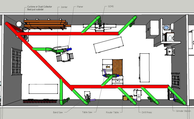
- Fire Safety
You need to set up your dust collection in a way that will protect against fires! If you have a unit where material can directly hit the impeller, then rocks and pieces of metal can hit that impeller, cause small sparks and those sparks fall into your sawdust and slowly grow into a disaster, often many hours after you leave your shop. If you have this kind of set up, you should never clean your shop floor or other areas that might have metal or stone bits with your dust collector. For this reason, most agree that dust collection bins should be metal. I used a 30-gallon metal trashcan on one unit and a 40-gallon metal trash can on the other, both with metal lids and metal flex duct going to them from my cyclone. That makes the dust more awkward to empty, but safer and the metal flex duct is much less expensive. With a two-stage unit using a separator or a cyclone before the blower this becomes less critical.
- Pipe Size
Always use the largest diameter duct that your blower can support with the least number of restrictions. If your ducting is too small, then it instead of your blower defines the CFM that your system can provide at your machines to pick up the dust. If your ducting is too large you might not maintain the airspeed needed to keep sawdust and chips from building up and blocking your ducting. Air engineers design dust collection systems to have 3000 feet per minute (FPM) airspeed to keep all entrained (moving) horizontally and about 4000 FPM to move it vertically. As discussed before we need at least 3 hp small shop dust collectors or 5 hp cyclones and then can only use 6" diameter duct for verticl runs which unless we use oversized blowers will only move 785 CFM. That 785 CFM is too little for the 1000 CFM required for good fine dust collection. Likewise, we have to do some careful measurements to pick our horizontal duct as we need to keep the size large enough to carry our needed air volume without getting so large that the air speed falls below 3000 FPM or we get piles that pose a fire danger and can ruin our equipment when they break loose. For almost all small shop systems this works out to using the same sized duct for the mains as the down drops. With the oversized blowers used in my designs you can safely move up to 8" diameter mains. I passed on the 8" or 7" mains when I found the fittings too expensive, so in my shop I use all 6" diameter duct for mains and downdrops. It consistently provides over 1200 CFM at all my tools with plenty of airspeed to keep all clear.
- Ducting Resistance
Ducting resistance is known as static pressure. Even a short run of duct that is too small for a blower will cut the airflow down to the highest speed that pipe can sustain. The impact on most hobbyist blowers is terrible. A 3/4 HP blower with a maximum airflow of about 600 CFM will rarely provide more than about 300 CFM real air flow when connected to a 4" pipe. On that same 4" ducting a 1 HP and larger units still only move about 350 CFM. A 2 HP dust collector capable of 1200 CFM is lucky to provide 450 CFM. Bumping up to 5" pipe supports 545 CFM. Bumping up to 6" pipe supports 785 CFM, but anything less than a 3 hp blower then lets the pressure and air speed fall enough that we get plugging in vertical runs. Clearly we need 4" diameter duct for good chip collection and at least 6" diameter duct with oversized blowers for good fine dust colleciton.
- Ducting Reductions
Unlike big industrial sites, most hobbyists should run the same sized ducting, fittings and hose right up to their machines. Don't do like many and run a 6" or 8" main trunk line then come off with smaller duct or flex hose. The top magazine rated cyclone vendor designed and supplied the ducting for their cyclone I installed in my shop. They had as small as 1" diameter down drops which measured with only 22 CFM airflow letting all collect in the mains. When I opened larger ducts the piles in the mains slammed down the ducting so hard they blew apart my joints, ruined my blower wheel, and destroyed multiple filters in less than six weeks use. Smaller pipe kills the airflow needed to keep the air in the mains moving fast enough to avoid plugging and building up dust piles. You have to keep three 3" ports open at once or two 4" ports to avoid the plugging a 6" main and even more open for larger mains. Having so much open often kills the airflow needed to collect the fine dust. If you use standard hoods you should still convert over to 6" ports. Even reducing ducting size right at the machine for the shortest possible distance to a small 4" port will still kill system performance. The smaller ducting, flex hose, and small ports limit the maximum airflow just like we proved in that little air test sucking experiment! If you do change size ducting, use a big enough blower to support opening multiple blast gates and appropriate connections for enlarging and reducing:

My friend Sugi found a better way to do ducting reduction and expansion. His mixed combination of Imperial and Metric sized ports on his tools required lots of different reducers and expanders to work with his 6" mains. He found a very elegant solution that gives far better airflow than we get with even the nice tapered reducers shown above. Kanaflex makes a polypropylene rigid duct hose they call Kanaduct with interlock construction which allows the inside diameter to be changed by twisting the hose. This duct starts off as a flat strip rolled into a spiral. On one side of the strip is a male rib and on the other a female socket very similar to zip-lock bags. Depending upon direction of twist this duct either expands or contracts in diameter up to about 50%. This results in very smooth clean transitions without all the nonsense of expensive transitions. The retail price per meter is abot $24 which is cheaper than having to buy metal reducers and flexible hose. We can easily make long transitions that very effectively reduce pressure loss.
- Ducting Material
The next most important aspect of building a good ducting system is which type of ducting material you will use and still ensure the level of safety in your shop. If your shop is going to be subject to a building inspection, fire marshal inspection or insurance inspection, then you need to use all steel ducting. Almost all small shop dust collectors and cyclones are gravely underpowered, so we need to use the smoothest pipe we can get to minimize resistance that rapidly kills these lower airflows. To minimize resistance, the interior of the pipe needs to be as smooth as possible and you need long smooth sweeping smooth bends on all your elbows and wyes. Also, air needs to spill over the joints, not ram into them which causes high resistance and causes strings and such to get stuck in the duct joints. There are lots of ducting choices and often we slip into a mode where we think if something costs less it is not as good. The smoothest walls that make for the least resistance come with using plastic coated pipe and fittings such as PVC pipe or plastic coated metal or wood duct. The next best is smooth walled laser welded steel pipe followed by top quality metal spiral dust collection ducting and fittings then HVAC metal duct, followed at a far distance by corrugated metal pipe and flex hose. Airflow depends upon ducting friction. Here are the Hazen/Williams friction factors for various duct types (a higher C number is better).
Duct Material H/W Corrugated Steel Duct 60 Spiral Duct 90-100 Laser Welded Steel Duct 110-125 PVC 146 Notice that corrugated duct is so restrictive it should never be used! The same is also true of flex hose that has a rough interior. Also notice that in spite of some vendor claims, these values show that PVC moves more air with less friction than even equal sized spiral ducting.
Unfortunately, many wrongly think that they can easily use HVAC ducting for their dust collection systems. HVAC air blows in the opposite direction as it does during dust collection, so every joint is backward. The good news is all but HVAC wyes can be turned around to get the air moving the right way. We can either use expensive dust collection wyes or do the metal working to change the male and female ends.
We need to be careful when buying either dust collection ducting or HVAC metal pipe. We can easily spend a small fortune and still not end up with a system that works efficiently or is leak free. Also, most "official" dust collection pipe uses proprietary connectors and sizes that often limit your expansion to working with just that firm. With special tools required to make junctions, you also end up generally paying for a number of custom made parts. I started off using HVAC snap lock duct and quickly learned I don't like fighting with snap lock and I had to use the heavier 26-gauge because just like with one of the cyclones I built, standard 30-gauge collapses if the system gets turned on with no blast gates open. There were other problems with HVAC ducting. The HVAC wyes need the male and female ends reversed. I had so much ducting the cost to buy actual dust collection wyes with the correct ends was too high, so I invested around $100 buying on sale an inexpensive Harbor Freight knockoff of a Pexto machine that let me crimp the female joints into male then flatten and expand the male joints into female. Also, HVAC systems use such much higher volumes and lower pressures that are not as affected by tight turns, but the tight turning HVAC elbows add too much resistance for use with dust collection ducting. Purchasing long radius dust collection elbows was also cost probhibitive so I instead used two or three swivel HVAC ducts or used two 45 degree ducts with a straight in between to reduce resistance. With my constantly adding and changing tools as well as my shop layout, I rapidly grew to hate the HVAC snap lock pipe, so shifted to use spiral pipe which actually cost less and was easier to work. My new home with its own shop in a large separate building and elevated floor inspired me to foolishly place the ducting under the floor. After living under the crawl space with every change, I said never again, plus there were condensation problems that ended up rapidly rusting and corroding my duct. Another move left all my ducting for the new home owenr and put my shop back in a bay of my garage with my doing all over again. I was back to a garage based shop, so had to start all over again. I considered building square or rectangular ducts from Melamine coated particleboard because that material is inexpensive and very slippery so would have little resistance. After making a test run I gave up as that was too much work. One of my friends showed me an article that debunked the static explosion problems with PVC, so I used the thinner PVC pipe that is readily available and inexpensive in my area due to all the agricultural irrigation (see my PVC site if you want to do "magic" with fitting PVC into your ducting). The low cost sewer and Drain (S&D)PVC (plastic) pipe worked so well I used to recommend the PVC ASTM 2729 "Sewer and Drain (S&D)" pipe for most small shop woodworkers. The 2729 PVC pipe and fittings cost far less than metal or standard schedule 40 PVC, are much stronger, don't leak like metal pipe, and have a much lower coefficient of friction than even spiral metal ductwork. The 2729 PVC is rated for many times the pressure that even large industrial blowers generate. I've seen no flex with my PVC pipe even when doing testing on 10 hp blowers driving a 16" impeller. PVC then was one of the best small shop dust collection material choices because it is smooth, far stronger than most HVAC metal pipe or spiral pipe, costs less, and fittings are a fraction of the price. We then had a flood in our home from a burst water pipe. My insurance inspector said I could either replace the PVC duct and cardboard dust bin with metal or lose my tool and any fire coverage from a garage based fire. My State inspector also said any flammable ducting materials are totally inappropriate and will not pass either a building, fire marshal or insurance inspection. Health problems required me to retire my shop so I gave away my cyclone and PVC ducting. After a far too long break my health has improved enough that I can resume some limited woodworking. In the interim the price of oil has gone up so much PVC pipe costs more than HVAC pipe or even good spiral pipe. With limited ability and patience to play with ducting I am now using higher end steel sprial ducting that mates with cam action sealing laser welded steel duct fittings. They are very expensive and far beyond what I could afford when I first started doing woodworking. - Ducting Cost
It is best to buy your dust collection pipe, fittings and flex hose from either a firm with free shipping or from a local supplier, otherwise you can easily pay nearly as much for shipping as for the cost of the ducting.
- Ducting Connections
Making your dust collection connections can be done with glue, screws, special duct sealant, and many other things, but most find that slipping all together works best. This is especially true if you buy duct with the built in seals. They cost more but make tight joints that normally don't need anything more to hold them in place with a good seal. Most agree that not gluing PVC is by far the preferred way to go, as you may change your mind on your shop arrangement, and you will for sure eventually catch something that clogs requiring you to take one or more joints apart. I found on both the metal and PVC pipe, use of standard 2" aluminum duct tape found in home and HVAC stores provides great seals that do not leak or come apart. Be careful when handling this aluminum tape as it is very sharp! Permanent joints are better sealed with either duct sealing compound or polyurethane caulk.
Although the Kanaduct shared above in Transitions works well for joining different materials and diameters, this can be a little pricey and requires mail ordering. John Koster reminded me that standard plumbing neoprene "no-hub" connectors provide a good less expensive locally available solution for those who need to connect dissimilar pipe materials. These "no-hub" connectors come sized to mate Cast Iron/PVC, Steel/PVC, and PVC/PVC. These connectors are easily placed and removed for access, provide a good seal on an adjustable range of diameters, and act as good "dampeners" for vibration and noise transmission. - Duct Hanging
There are lots of ways to mount your ducting to the ceiling or wall. After years of changes my technique now uses heavy wide long nylon cable ties and screw in mounting brackets.
- Wire
The traditional approach for hanging duct some distance from the ceiling is to attach galvanized wire to the ceiling or to a metal pipe then around our ducting. This works well, but is difficult to adjust without a lot of practice or use of expensive turnbuckles.
- Metal Strapping
The longest lasting and least expensive to install hanging system uses perforated rolls of galvanized sheet metal plumbers strapping. To mount flush with the ceiling you can make a U and secure both ends with screws. To hang you can mount to the ceiling, use a tape measure to get a consistent distance and equal length loop and then bolt that tape around your duct.
- Nylon Cable Ties
Amazon carries wide heavy duty nylon cable ties that work well to secure ducting right to the ceiling, but these don't work well if your ducting hangs well below the ceiling. Although the nylon ties will eventually get weak and fail, most change their ducting and tools far more often than the years it takes for the ties to get brittle and fail. Here are pictures of ties and matching mounts that you can order from Amazon. If you use these links a small commission comes back to help support these pages. If this is a concern, you should use the galvanized perforated metal plumber's strapping.
The easiest way to install the nylon cable ties is to use screw in mounts designed to work with these ties. The nylon cable ties are what gets used in my shop with its 8' high sheet rock covered ceilings to hold galvanized spiral duct. To minimize dust going into the down drops my mains are a 2x4 spacer below the ceiling with all down drops first going up to flush mount on the ceiling then dropping down to the tools. The sprial duct has one end crimped to form a male end which always go placed closest to the dust collection system. You can either use two forty-five degree ducts with a straight spacer, two swivel ducts or dust collection long radius elbows. My preference is the higher cost long radius elbows from a ducting store. Likewise, you either need to buy your wyes at a ducting store or use a roller and crimper to reverse the male and female ends. Layout your ducting design then follow that design using chalk lines on the ceiling to show the layout. Then use 2" sheet rock screws to secure the heavy nylon cable tie mounting brackets into the supporting studs. Thread the wide long nylon cable ties into the mounting brackets without connecting the ends except on the starting tie. The starting tie gets a large loop to hold one end of the duct. Slip the duct into the loop and use an adjustable stand to hold up the other end of the duct with spacer in place when needed. Secure the tie in the other end to loosely hold the duct up. Connect the rest of the ties loosely. Slip the male ducting end into the prior duct segment then use heavy aluminum tape to secure the joint. After all ducting is up with the connections sealed, I then cinch up the cable ties to pull the ducting to my ceiling or spacer. As a tool nut my ties get secured with a nice pistol type nylon tie gun that cinches up the ties and clips off the ends all nice and even. It can work too well and tighten the ties so much it is near impossible to remove the spacers, so just tighten to snug, not tight. - Band Clamps
Another approach is to mount blocks with regular stainless steel band clamps. The clamp threads through a thin slot I cut in the side of the block. I then secure that block to a stud with a deck screw. That screw also secures the open edge of the block and squeezes down on the clamp to hold the clamp in place. This same approach works equally well with the nylon cable ties.
- Wire Rope
Another solution for hanging duct is to use stranded metal cable (called wire rope) with special clamps that let you adjust the length. A number of firms make and sell different types of cable connectors. The simplest and most difficult to use are the "8" shaped metal ferrules that you squeeze onto the cable with a crimping tool known as a swager. I've been making massage tables using this kind of system since the early seventies and own three different types of swaging tools. Even with a lot of practice I either make all on a template or end up having to redo too many. Most boat supply stores sell both the cable and ferrules, or you can get them from a cable supply store. I bought on-line a large spool and a pound of ferrules for what it would have cost me to buy just a few pieces from a boat store. I've only helped do one shop with very high ceilings and this stranded cable. Using the compression ferrules was such a pain to get just right if I had to do it again I would pay for the adjustable fittings.
- Suspension System
A far more elegant and expensive solution for hanging duct is to use wire rope with special adjustable fittings that allow you to quickly do the installs and set the pipe height. Just about all HVAC supply stores and ducting supply firms offer one or more of these types of systems. One of the better known that many woodworkers have used successfully is the Gripple System.
- Wire
- Pipe Under Floor
Although most prefer to hang their ducting from the ceiling, there are also lots of ways to put your dust collection pipe under your floor.
- Subfloor
For those who have a shop that sits on a heavy subfloor, it can be very convenient to run your ducting under the floor. I like a wooden sub floor in a shop because it is much easier on the legs. Both of my two larger shops had nice sub floors and I ran most of the ducting under those floors. For my first, I carefully designed and put every hole just where it needed to be. That worked for about two weeks until I bought a few more machines and ended up having to crawl back under the floor and redo all. For my second shop I put a fitting every six feet along the walls and down the center of the shop. Each had a plug and was covered by a piece of tile, so when I needed to make a change, I just had to lift the tile, remove the plug and put in a flex hose to the machine. That worked pretty well.
- Concrete Slab
Cost and convenience often end up with many shops having a concrete slab floor. If you are fortunate enough to be building your shop from scratch, you can build in some trenches. I've helped build one of these type shops and did most right, but also learned a few lessons the hard way.
-
Because I included both a sink and small shower, I ran water and drains in dug trenches, plus another trench to bring in power. Living right on the edge of an industrial area, I was fortunate enough to be able to bring in three-phase power. The floor I built was put over those utilities on well-tamped ground covered in 4" of crushed rock then a vapor barrier.
-
I also tapered each of my trenches with just a little grade and put drains at the end of each trench. The mistake I made with those drains was sharing them with the sewer drain without a water trap to kill any odors. I ended up having to reconnect them to my yard drains instead.
-
I built my trench with a lip that will hold a 2x8 flush with the rest of the floor. That let me cover up the trench and not create problems moving around my equipment and tables that were on rollers. If I were to do this again today, I would make the trench sized with a lip to use the surplus aluminum raised computer room floor tiles. These are much stronger than the 2x6 and much easier to install and remove for access.
-
Into my trench went the ducting, compressed air, and power. I protected the power by putting it in well-sealed PVC coax. Had I used that raised computer room flooring my trench would have been big enough to also include lines for my shop vacuum, drainage, and possibly water if permitted by my building codes.
-
 I carefully framed in the trench to make a nice rectangular pour. Even with rebar sides, my straight walled trench cracked. Those cracks made for a moisture problem that was not compatible with my galvanized ducting. A far better way to go is to make a nice smooth pour as shown in the picture.
-
- Computer Floor
We are in an interesting time right now where the computer world is changing so fast that this leaves an opportunity for woodworkers. There are huge quantities of surplus very well made raised computer floor that provides a raised floor of 8" to 12" to permit running electrical, communications, cables, etc. under the floor using easily removed tiles mounted on stands. These surplus computer floor squares and uprights are readily available for little cost. They create a floor that is nothing short of incredible for woodworking. You can put in your ducting, power, water, and whatever else you need or want to run under that floor, then have easy access to make changes.
- Subfloor
- Fire Safety
- Ducting Components
- Ducting Accessories
There are many nice accessories that you can use with your dust collection, but realize that even with these accessories a dust collection system does some functions poorly.
My first accessory mistake was buying a transition that mated my 4" dust collection hoses to the tiny 1.25" port on my band saw. So little air was moved I went back to using my powerful shop vacuum on all tools with small ports. I also bought the 5" Delta replacement port for my band saw lower port, plus used Lockline adjustable pick up duct with hood pick up above by the table attached to my strong shop vacuum. The rule is never hook a dust collector or cyclone to any size pipe less than 3" in diameter.
My dust collector came with an upper and lower filter bag that worked poorly and required constant emptying because I made lots of dust from preparing rough stock. My next mistake was buying a metal trashcan and trashcan separator lid. The trashcan separator reduced the fire risks and saved on emptying the dust collector. When I bought a set of air gauges and did some testing, I realized that my trashcan separator was not good news at all. It pulled the real 1100 CFM I got from my dust collector through a 6" test pipe to under 450 CFM.
My next mistake was replacing the dust collector bags with an easy to empty lower plastic bag and fine oversized fine upper filter bag. but I still constantly struggled with the new upper filter bag getting so full of dust it felt like cement and would barely pass air. Every filter cleaning left me and my shop covered in the fine dust I bought that fine bag to avoid. I later learned during the medical air quality testing done on my shop that my so called filter was a sieve that freely passed most of the finest unhealthiest invisible dust.
I made my next mistake buying a "best" hobbyist cyclone system. It moved less air than my dust collector, just about half of what the vendor claimed in the advertising. That cyclone killed the airflow below about 450 CFM, plus did not move enough air to keep the ducting clear. After digging into the engineering behind cyclones, I realized that almost all small shop cyclones were copies of the same original design. That design was never made to be used inside with fine filters, so I designed my own more efficient cyclone. It works well to power my downdraft table, collect chips from my router table and larger tools, and pick up the leaves that constantly get blown into my garage shop. It also is a huge help in cleaning my shop when used with a ShopSmith vacuum attachment. Do not use a dust collector as a vacuum because any steel screw or nail picked up hits the impeller and can put a spark in the collection bin. Also, most dust collectors make poor vacuums because the airspeed is too low for good pick up. My cyclone moved more air and also separated off the material before it got to the impeller so worked well with my new floor sweep. I hot melt glued in big neodymium super magnets on the front of that sweep to collect nails and screws before they get sucked up.
Even with a good cyclone and vacuum, I found some tools still spray dust. When using them I wear my mask, open up the side door and garage doors and then run a big fan in the side door to keep that dust blowing outside. For quick cleanup after using these dusty tools I wear my mask, open all up with the fan running, and use my big compressor or leaf blower to quickly blow out the whole shop then turn on and leave on my ceiling mounted air cleaner.
- Blast Gates
You close the airflow to a machine with a blast gate. There are many different types of blast gates including many that can be opened automatically through electric motors, air pressure, and even hydraulics. The best place to put your blast gates is next to the wyes off your main line up high. The more open pipe or hose you leave exposed between the main run and the blast gate, the more resistance it causes. Also, if that pipe fills too much, opening the gate will cause all that material in the down drop to slam into the impeller potentially ruining motor bearings and even breaking impellers. It then goes into the filters potentially poking holes and greatly reducing filter life by requiring far more cleanings.
Many buy or make poorly designed blast gates and get very frustrated. Many of these gates, including expensive metal commercial gates, leak badly and we can make this problem worse by installing them backward. These gates come with a screw that pushes down on the slide portion of the gate to lock that slide in place. Many install these gates backward so the screw pushes the slide away from the vacuum source creating a noisy air leak. One system I tested had so many leaks from installing the gates backward that he had less than half the total airflow that we got after reversing the gates so they sealed well.
Also, many of even the expensive gates get clogged with sawdust that prevents them from closing fully. Most used a slide that slips out of the way leaving an open track that will pick up sawdust even if the gate is set with the slide pointing down. Every time you close a gate like this it jams sawdust into that track. Eventually you pack in the dust so tightly that the gate will not fully close, will jam, and can even split. You need to install the gates so the slide opens downward, but this often causes the slide to fall out on poorly made gates, so with these we need to clean often. I found a heavy paperclip and shop vacuum works wonders, but need to clean every few months. A much better design is shown here where the portion that closes goes all the way through ensuring there is no place for the sawdust to clog.
The only retail carrier I've found who that sells these types of "self cleaning" blast gates in 6" for an affordable price is Lee Valley Tools (search on blast gate). Otherwise buying this type of blast gate is difficult without a commercial license to buy from a wholesaler.
Because there was no available source when I needed my gates, I found Phil Bumbalough's Building a Blast Gate provides an excellent set of well pictured directions on how to make these types of gates. Making your own similar gate is fairly easy. The only changes to Phil's design that I recommend are using a split female PVC connector instead of pipe on the gates. The couplings let me connect directly and tightly to my PVC and metal ducting without leaks or having to use another often expensive and for sure bulky fitting. On a few of my gates that end up next to my machines and get connected with flex hose I instead use a short length of PVC pipe for the lower portion of the gate outlet. I prepare that pipe before gluing by first cutting six 2" long slits in the end made by my band saw in three cuts then wrapping that pipe with a heavy wire in a spiral that I hold in place with glue. This creates a threaded taper that lets me screw on my flex hose onto the pipe for an easy tight fit and no need for another expensive clamp. The result is tight enough that a piece of tape is ample to make a good seal.
There are many who are interested in having automated blast gates that open when you turn your machine on and close when you turn your machine off. This will help make sure you get good collection, but I don't recommend you turn your dust collection system on and off as too many on off cycles will soon ruin your motor. Not only does turning our blower motors on and off use up lots of extra electricity, the top motor makers recommend no more than six on off cycles an hour or our motors will get too hot and burn up. Regardless, you can make excellent automated blast gates. Two of my friends have built nice automated blast gates and shared how they were built and how to use them. The first was Jim Halbert in 1995 and shares on a YouTube video at (click here). The second is Alan Schaffter and he shares his information at (click here).
Blast gates work great if placed between your tools and cyclone, but work poorly for changing your air stream between filters and venting outside. You can use a couple of blast gates on the outlet side of your blower but they will leak badly. To not have these leaks you need a different kind of gate or valve. Nomal gates do not leak because the suction pulls the flat portion down tight to make a good air seal. With a gate on the blower outlet the air is blowing on the gate, so air pressure opens the gap in the gate and can spray fine dust all over. For these it is better to make a diverter valve as pictured below that will swing to make the air close tightly on one side or the other. The first is a wye fitting with a valve and these are easier bought than made because getting a tight seal is tough. The second is a simple box with a throw. or
or 
One other important note is don't go with the cutesy HVAC metal flanges on your blast gates that I see popping up on woodworking forums as a recommended way to make these gates. They do look pretty but greatly increase the cost of your gates, don't seal well, are razor sharp so will cut with even a small touch, and unless modified don't fit either standard dust collection pipe or even 2729 S&D PVC.
- Flex Hose & Hose Clamps
The internal ridges on rough or poorly made flex hose can create as much as nine times more resistance than smooth walled pipe of the same diameter. Even good smooth walled flex will increase resistance three or more times over straight duct. This resistance kills airflow, so when you use flex hose, always use minimum lengths and only use flex hose with smooth interior walls to get the best possible airflow from your blower. Additionally, there are flex hoses available with plastic reinforcement ribs, but these plastic ribs provide poor crush resistance and make this type of hose generate so much static electricity that it is not permitted in commercial shops subject to fire marshal inspections. Finding 6" smooth walled flex hose with metal reinforced ribs that can be grounded can be a price shock. Good flex hose costs considerably more than the bulk rough interior walled 4" stuff that many buy only to eventually learn that small diameter will not support the airflow required. I found Amazon.com, Wynn Environmental, and Northern Tool sell very good quality larger diameter smooth walled flex hose. Wynn continues to have the best pricing on hose if you buy 25' lengths. Lesser quality hose with rougher ribs can be purchased through Grizzly.
Although most buy stainless metal band screw type clamps for securing their flex hose, standard stainless steel band clamps work poorly. When we use normal clamps the hose reinforcement ribs create a gap which keeps the hoses from sealing tightly all the way around, so the joints leak air and fine dust. A bridge or wire hose clamp provides a much better seal as these clamps bridge over the ducting reinforcement rib to create a good seal all the way around. Amazon.com sells expensive good wire clamp that bridge over the ribs. Wynn Environmental and Lee Valley sell the best stainless steel bridged band clamps, but you need to buy these in either left or right handed versions to match the spiral on your hose. - Fittings
Types: Many choose to run to their local box store and buy HVAC (heating ventilation and air conditioning) fittings. For the most part these are a poor choice just as they are for ducting. Unlike the thinner 30 gauge ducting pipes these fittings will not collapse, but if you look closely many fittings are all made for the air to flow away from the blower. The result is every joint is backward where the air ends up jamming against an interior lip which causes extra resistance and can pick up debris. Most fittings can just be turned around, but some like wyes require changing the gender on each of end to keep from trapping sawdust and strings. I use a roller to flatten all the male ends and a crimper to convert the female ends to male. Moreover, few of these fittings seal real well or are that smooth inside. Many also have very tight angles and bends. The result in terms of efficiency is not too bad for each joint, but unless you are careful the total can add up to terrible performance. Many choose to avoid the work needed to clean up the HVAC joints by buying or making PVC fittings or using actual dust collection fittings that are smooth walled without the joint reversal problems.
- Wyes
You come off your main run with Wyes. There are many different types of wyes, but the best are going to be those that are smooth and either the most gentle angle or longest radius. Many choose to use the inexpensive sheet metal HVAC wyes found in home centers, but these have far more resistance and potential to cause plugging than what is appropriate for dust collection. As shown some configurations are far better than others.

We often use wyes on our down drops to split the flow to mate with two or more ports on a single machine. For instance the collection to my table saw starts with a 6" down drop that goes into a 6" blast gate, then a wye with one leg going to a 4" diameter port on the saw Shark Guard blade guard port and the other leg of the wye going to a 5" port on the table saw cabinet that I upgraded from its original 4" port size. In small shop systems when we calculate the overall static pressure we normally just add up the resistance levels for each piece starting with our tool hood, then ducting with fittings, then separator if used followed by filter resistance. Because both both legs of our wye are open at the same time past the blast gate we calculate the static pressure for these a little differently. We calculate the static pressure for one leg including tool hood then calculate the static pressure for the other leg with tool hood followed by dividing that total by two. If there are three ports such as on my band saw, we need to calculate all three legs separately, sum them up and divide by three. If we don't do this we get unreasonably high static pressures that do not occur in real use. If you want to make it easy on yourself and still get a workable number, just pretend that there is no wye and calculate static pressure based on having a single length of flex hose the same diameter as the down drop with a length the same as the longest leg after the wye.
- Elbows
You change ducting direction with elbows. As with wyes, there are many different types and the best are going to be those that are smooth and have the longest radius. As with wyes the inexpensive sheet metal HVAC units found in home centers have far more resistance and potential to plug. As shown some configurations are far better than others.
- Homemade Fittings
With the cost of both HVAC and PVC fittings so high, many choose to make their own fittings. I made quite a few of my own both in sheet metal and in PVC. At first I used a free sheet metal transition program I found on the Internet that let me print out full sized patterns and then cut out my own patterns in either PVC or metal remembering to add for the PVC extra thickness. Lots of work with my metal sheers and soldering torch or heat gun and PVC cement created whatever custom fitting I wanted. Eventually I changed to two different approaches after realizing I was mostly making 45 degree wye fittings in 6" PVC. I set up my lathe with a 6" piece of PVC made into a sanding drum by slotting then wrapping tightly in heavy sandpaper. The slot keeps the final drum diameter with sandpaper the same as the rest of the pipes. I use a protractor to set the angle at 45 degrees with a jig to move pipe into that piece. I also have a stubby precut pipe piece that I lay on other pipe where I want to mark a hole that gets cut with a saber saw. Just a little hand sanding on the hole leaves a near perfect joint. The other nicer approach I use is a little more work and takes far more skill, but makes better joints and allows using longer pipes. For this one I also mark where I am going to cut my hole in the pipe, but make the cut 1" all the way around too small. I then heat the pipe with a pair of heat guns and use a custom made wooden mandrel that I slip into the hole from the inside pushing out a perfect female fitting that when cool can be used to join a pipe.
Stan Harder developed a resource to help woodworkers save money when building their PVC dust collection transitions. His free online software program Harder Pipe Joint Template Software creates templates to assist in cutting PVC pipes that can be joined together at different angles to let us have joints without needing to buy expensive pipe fittings. He has had good success using the thicker CA glues used by wood turners to make PVC joints and they look really good. I would strongly recommend adding inside and out on his joints a strip of the 2" stick on aluminum duct tape for grounding. Additionally, for my similar joints I wrap and CA glue some heavy copper grounding wire around the PVC joint that we can use to screw in flex hose creating a solid joint that seals well with an inexpensive hose clamp. Thanks for sharing Stan!
- Wyes
- Transitions
 You need a way to go from your 6" round ducting to your filters, your blower, your cyclone, and some tools that have square or rectangular duct. These pieces are called transitions. There are three relatively straightforward approaches to getting a transition. The best is to build a transition that makes a perfect fit. Next best is to buy an HVAC fitting that is close then modify it to work. It turns out a 4" x 10" to 6" round HVAC heating register fitting easily changes to be a 4.5" x 9" to 6" transition. Likewise, I found by measuring the perimeter of the blower outlet that it just so happens that each of my designs is a perfect fit with one of the various sized round transitions when you compute the circumference. Least best is to change your tool or other unit to fit a standard transition. You can follow the below information to make your own transition. If you would like to learn more on making a transition and have a spreadsheet to calculate all of the specific distances, please see Joe Emenaker's Transition Page.
There is a fairly simple but lengthy way to build a transition. Sheet metal workers call this an evolution. Because my plans are scalable, your evolutions will change based on cyclone and blower sizes. I've done one by hand for a 13.5" and another for an 18" cyclone.
Ronald Scalise shared an easier jig technique he learned from a friend to quickly layout a transition for metalworking. Ronald said he is more used to working in thousandths of an inch and was amazed at this technique because it comes out just right every time. Ronald says, "You need three things, a wood dowel a round disc the size of your incoming duct and a wooden rectangle the size of your inlet. Find the center of both the disc and rectangle then drill a hole through each and connect them using a dowel. The dowel needs to be exactly the length of the desired transition. Place the jig on the sheet metal and carefully roll it around using the jig as a ruler to mark your lines on the sheet metal. The result after marking all four sides of the rectangle is a perfect layout that only needs cut and formed to be done.
My friend who has done this for years made this look too easy. I ended up with way too many lines on the sheet metal my first try. Although it turns out to be easy, I do recommend starting with some practice paper to get the technique down. It only takes a few tries to get it down pat. I learned to start with the longest side and draw a line then follow the circle around as I turn the disc."
 The traditional way to build a transition is fairly simple and also works well, but takes more time. By drawing a view of that fitting looking down at the circular inlet you can see a circle and the rectangle that it joins.
 Add to that drawing the fold lines used to transition from the circle to the rectangle. The fold lines in this view are red. Looking at these fold lines from the circle inlet gives us the actual length of a base of right triangle whose height will be the length of the fitting.
 The diagonal for each of these right triangles is the actual length of the line used to layout the metal cutting/folding diagram. You can either use math to calculate the lengths of these fold lines or you can get them by drawing a right angle. This angle forms a right triangle as tall as the height of the fitting and base taken with a set of dividers from that view picture. You can then use dividers to go from the top to the base to get the diagonal. The more fold lines, the smoother your circle. Most metal workers find it is easiest to divide a circle into 24 parts making for 24 fold lines. Draw a fold line from each corner to the seven closest circle divisions. This means the first and seventh line each end up going to two corners. Once you have the lengths of the seven fold lines that go from each corner, you have all it takes to layout your cutting diagram.
 This is all the information you need to actually draw your layout for your cutting diagram. Start by drawing with a horizontal line that is the length of the longest side of the fitting rectangle. Use a compass to set the length of line one. Swing arcs from either end of that horizontal line to set the top of that triangle. I used a second compass that is set to the length of an arc that is 1/24th of a circle. To get that length I drew a full sized circle, then divided the circle into sixths, then twelfths, then twenty-fourths. If you don't know how to do this, you have to look it up yourself. (Radius will give you sixths, splitting any angle will give you 12ths, then one more split for twenty-fourths.)
 Carefully in order add the lines that go to that corner joining the first two to make a triangle. Each successive line makes another triangle whose base equals the length of a segment that is 24th of a circle.
 After drawing seven lines, the eighth line starts from where the seventh ended and creates a triangle whose base is the shorter rectangle size.
Anyhow when it is all said and done, the result plus 3/8" of soldering tabs gives the transition duct. I only showed the soldering tabs for the sides. You also need them for both the circular part and the rectangular part. I used those extra tabs to solder a 2" ring onto the circular part to mate with my PVC.
- Ducting Accessories
- Tool Ducting
Each machine needs the dust collection to protect, control and deliver good fine dust collection. Each machine requires appropriate hoods to keep the airflow from our blades, bits, cutters, belts, motor fans, etc. from launching the fine dust before it can be collected. These hoods need to control the dust and then deliver it right to the dust port for collection. Sadly, most small shop tools come with internal ducting, hoods, and ports far too small and too restrictive to effectively protect, control, and deliver the fine dust. That means we almost always have to do extensive tool modifications. In some cases we cannot amply fix our tools, so we must use them with a powerful downdraft table. Some even a downdraft table cannot help, so these either need used outside or replaced.
- Dust Ports
Most small shop users will have to upgrade their tool dust ports themselves and use the wrong types of ports. Sucked air comes from all directions at once, so if we use just a pipe going into our tool, what happens is the air coming from the sides or backside of the pipe picks up speed then rams into the air coming in from the front. This creates lots of turbulence, resistance and significantly reduces airflow. So although many use flat HVAC connections it is far better to use actual dust collection ports that have a really nice curved inlet. A bell shaped (hyperbolic) curve eliminates most of the problems from the air coming from the sides and back to reduce resistance and increase flow. I like the Lindab and Nordfab smooth walled laser welded steel take off flanges plus they and have a built in gasket. Also, these are very good looking smooth strong ports. Note it does not take much curve at all to make a huge difference.

Most small shop users also mess up their ports. Most stationary tools need more than one port or hood instead of just a bigger port. For instance my table saw came with a single 4" diameter port. The stock blade guard sprayed fine dust all over, so after doing my homework I upgraded to a Lee Styron Shark Guard Whale sized over blade guard with a 4" port. That left me with a 4" port for my blade guard and a 4" port on my saw cabinet. I needed to figure out how much if any to increase the size on my cabinet port. The total combined area of the ports should closely match or just slightly exceed the area of our ducting. Rather than have to guess, I built the following chart that gives the combined areas for different sizes. We use this chart to pick two different diameters that equal or slightly exceed the area of the incoming ducting. The green shaded blocks are what most who use standard 7" diameter duct should use. The blue shaded blocks are what I use for splitting 6" duct. For example, let's connect my cyclone to my table saw with a 6" downdrop. This table shows my 6" diameter ducting has a cross sectional area of 28.27 square inches. I look at the table and see a 4" blade guard port with a 4.5" diameter port is the closest solution for my saw cabinet. I cannot affordably get 4.5" diameter duct or ports, so next best was a 5" diameter port which is the size added to my saw. So my saw got upgraded with a 5" cabinet port.

I heard from Steven Thompson that a good source for these parts and other DC ducting components is Mechanical Equipment in Georgia at (770) 963-6226. He said they have great prices and are willing to ship UPS.
- Dust Hoods
Dust collection hoods and pick ups are one of the least explored areas in small shop dust collection, yet one of the most important. Although many vendors would like us to believe good fine dust collection is all brand new and about as complicated as rocket science, the reality is we have decades of air engineering experience that show just what we need in terms of our hoods and airflow. A good hood must do the following things:
Safety - A good hood needs to provide a reasonable measure of safety. This means it helps us keep away from our blades, bits and cutters while also protecting us from kickback and flying debris. For saw blades I strongly recommend use of hoods that incorporate at least a splitter or riving knives plus use anti-kickback pawls. Our hoods also need to be made of something strong enough that if things go flying we get good protection. I strongly recommend hoods be made of either metal or the polycarbonate plastic used in safety glasses, bulletproof windows, etc. I made the side of a blower from this type of material to see when it was time to clean the impeller. One of my test impellers exploded inside my blower. That 1/8" thick polycarbonate plastic held up better than the metal parts.
Visibility - A good hood also in my opinion needs to let us see what we are doing. Strangely, some saw blade and router guards are smoky or solid steel like the one that came with my European saw. I admit my saw guard soon got removed and ignored because taking it on and off to ensure my cuts were aligned correctly was too much trouble. I strongly prefer a clear polycarbonate plastic saw guard because it gives excellent visibility and minimizes a buildup of static adhered dust so we don't have to do a lot of cleaning.
Chip Collection - A hood also must provide good chip collection meaning collect the same sawdust and chips that we would otherwise sweep up with a broom. It is real simple. Our saw blade tips along with many of our other blades, bits and cutters launch dust at over 100 miles an hour. Even a powerful cyclone like my design only moves air at about 60 miles an hour. Unless our hoods block the fast moving airflows, we lose and are going to have sawdust and chips all over.
Fine Dust Collection - For those who want good fine dust collection, a good hood must also move enough air in the right places. If our tools are made from the ground up to totally trap all the sawdust and chips we make then a good shop vacuum will provide excellent dust collection. Because most of us use do not use tools built from the ground up for good fine dust collection we need to instead use a different approach. What decades of air engineering found works with our older tool designs is having hoods that block the fast moving streams. These hoods then also must move a large volume of air around the working areas of our tools. We know that the slightest breath can move the fine airborne particles, so to keep the fine dust from being blown all over our shops, we need to surround the working areas of our tools with air moving fast enough to overcome normal room air currents. Again the research followed by decades of refinement show what we need in terms of hoods and what is needed in terms of total airflow. It only takes about 50 feet per minute airspeed to overcome normal room air currents, but we have to provide that airspeed over such a large area that we need about three times more total airflow for good fine dust collection as we do for good "chip collection". Because air at dust collection pressures will barely compress at all, any undersized hose, duct, or port will restrict our flow. This means almost all of our typical 4" tool ports and ports on our 4" hoods must be need increased to 6" to carry ample air. For tools with two ports, we generally need a 6" down drop that ideally splits into a 5" and 3.5" separate hoods. Since the 3.5" ports and ducting is near impossible to find, we still can go fairly well using a 4" instead. I originally thought I could get by with using my existing 2.5" port on my splitter mounted blade guard on my table saw. The CFM Requirements chart showed I needed at least 350 CFM, but testing the airflow with that smaller port showed only 183 CFM. In short, for good fine dust collection we almost always have to rebuild our hoods and use larger ports.
I recently did air quality testing all over the State of California. One of these tests was at an engineer friend's shop with the testing coming out worse than ugly. He carefully followed my instructions from these pages building his own cyclone from my plans, upgraded to a big 16" blower impeller and built one of the prettiest carefully laid out metal ducting systems I've seen. Without doing any woodworking at all, our just moving around in his very clean looking shop stirred up enough of the fine invisible dust that his shop failed the EPA, medical and European air quality standards. I saw the problem but rather than tell him what was wrong we then did a standard test. We started using his table saw to cut 54 linear feet of ¾" thick MDF. Within seconds his shop air quality went well over fifty times worse to exceed the OSHA air quality maximum. I showed him what was wrong while his big exhaust fan and cyclone rapidly made the air quality safe.
The problem was the normal. Decades of air engineering show that if we do not capture the fine dust as it is made, we are going to fail the air quality test. The only way to capture the fine dust as it is made is to start with hoods that block the fast moving air streams. His dust problem was simple. His big new over arm blade guard was wide open in front so launched the dust off the tip of the saw blade right out under his guard. A 3450 RPM blade speed with a 10" diameter blade creates a 102 miles an hour air stream. His saw pulleys increase the blade speed closer to 4000 RPM so the blade tips launched the dust even faster. A typical dust collector or cyclone only moves air at about 40 miles an hour. With the hot rod oversized impeller on his cyclone, he was got 60 mile per hour air speed which had zero chance of capturing the well over 100 mile an hour dust stream. To effectively control the fine dust as it is made we must have hoods that mechanically block all the fast moving air streams or there is zero chance of effectively capturing the fine dust before it escapes collection.
 Shark Guard - My friend suffers from a common engineer disease meaning he is a touch obsessive sort of like a mule is a touch stubborn. He was really upset at that air quality test and soon called me back ordering me to give his shop a retest. In place of the blade guard that came with his over arm blade guard system my friend added a pretty amazing product. He replaced his over arm saw guard with a new Shark Guard pictured here made by Lee Styron. That guard rested on the wood and blocked the fast moving airstream that was spraying the fine dust all over. The bottom line is we again tested his shop and with that guard in place he got none of the dust that sprayed out all over in front of his saw and his air continued to test clean. Frankly, I was so impressed that I contacted Lee and ordered up the works for myself including his 4" dust port, tail gate, and special splitter with anti-kickback pawls that fits my European saw plus chose to have the metal parts in a bight easy to see safety red.
In addition to having good collection over the saw blade, it is even more important to have good collection below the blade because most of the dust from table saw use gets sent downward. Cabinet saws enclose the lower portion of the saw and generally come with a 4" port in the cabinet. A 4" port will only support about 350 CFM, but the airflow charts say we need 550 CFM for good fine dust collection. This means we need to open the port below our saws to a full 5".
Contractor saws also need good collection below the blade, but most lack the enclosures needed to control the dust sprayed below the blade. This makes collecting the dust from cabinet saws one of the more difficult dust collection challenges. Some have successfully used large magnet signage material to seal up the holes, but the bottom line is the only way to get a contractor saw controlled in terms of fine dust is to use a good blade guard like the Shark Guard mentioned above plus use coverings to enclose the saw base with a port for your dust connection. There used to be excellent magnetic attachments that did this but that firm is no longer in production so I recommend that you make your own coverings out of either metal or thick plastic.
Our chop saws, miter saws, sliding compound miter saws and radial arm saws all pose one of the more difficult fine dust collection challenges. The traditional solution sets up the blade guard connected to one leg of a down drop and the second down drop leg connected to a hood that sits behind the saw. This solution only works if you have a saw with a big blade guard port or can modify your blade guard to handle at least a 3" and preferably 3.5" or larger port. Most of these saws only come with a small vacuum sized port that cannot be easily modified. The best way to tame tools with small ports is to use a strong shop vacuum attached to the small port and connect your dust collection system to a large separate hood. Both need to run at the same time to get good fine dust collection. Nothing short of a strong vacuum generates the pressure needed to pull the air through a small blade guard port. We need preferably a 6" port on a rear hood to pull in the spray plus the fine dust.
I personally made my own shell out of a large plastic wash tub that only cost a few dollars. I cut a hole in the back bottom that was 4" in diameter then warmed up that plastic with my heat gun. Once it was a bit soft I worked a slightly tapered wooden form I made on my lathe to make a rear port that a flex hose would slide over. I also mounted my square wash tub to the rotating portion of my saw so when the blade rotates the tub stays centered behind the blade. Pictured to the right is a commercial Rosseau hood that does the same job. I wish it had a 6" instead of just a 4" port.
If we don't have good hoods on all our tools that control the fast moving airflows and move enough air, there is no chance of getting good fine dust collection. Fortunately, the better air engineering firms who certify that their customer shops will pass the air quality tests have been kind enough along with the EPA to share different hood designs that we know work well. Each of these hoods does a good job catching the fast moving heavier sawdust and chips, plus mechanically blocks the fast moving air streams. Even with good hoods, that still leaves most small shop dust collector and cyclone users in trouble because our vendors sell us equipment that moves about half of the maximum airflows they advertise. These lower airflows leave us with a bad false sense of security, meaning clean looking shops that tend to build up dangerously high amounts of fine invisible dust. AAF was kind enough to let me share one of their publications with their designs for dust collection hoods. I also have slowly been adding other hood designs that work well:
AAF Hood Design suggestions
Other professional hood designs:
(Note: 3.5" ducting is difficult to find so you can substitute 4")


Random Orbital Sanders NIOSH Recommendation
The dust generated by random orbital sanders is sometimes controlled by a vacuum in combination with a perforated sanding pad. The vacuum draws wood dust up through holes in the sanding pad. It was found that, in spite of this control, large amounts of wood dust were still emitted into the workroom. Adding more suction to these units causes the sanding pad to be pulled to the work surface making the tool difficult to use and potentially damaging the piece being sanded.
To alleviate this problem a slotted sanding pad provides up to 90% better fine dust control. Cutting curved slots into the sanding pad as shown relieves the pressure caused by the extra suction and provides additional dust control at the pad edges. This change does not interfere with the operator, requires no special maintenance and is inexpensive to make. This dust control device is not currently commercially available, but is patented so you can make these changes for your own unit but cannot go into commercial production.
Shaper NIOSH Recommendation
Wood shaper emissions are usually controlled by an exhaust hood located at the back edge of the work table which allows the operator to freely move the work piece over the table. Placing the exhaust hood nearer the cutting head would maximize dust collection; however, this would restrict the operator's freedom to move the work piece.
To overcome this problem, a hood extension with a flexible face opening is added. The flexible face opening consists of cloth-covered chains that allow the wood to pass through, but stops the wood dust particles. The extension also increases the hood face velocity by minimizing the open face area.
- Dust Ports
- Static Electricity
There is always someone who will bring up the concerns about duct static potentially causing an explosion when you use PVC pipe. PVC pipe is an excellent insulator that will build up a static charge, particularly in a dry cold climate. Although that charge can shock you, the experts say it is not ample to cause an explosion in hobbyist based systems. Dr. Rod Cole wrote an excellent article in Fine Woodworking that debunked the static myth with PVC pipe. He also posted that article on a woodworking forum and gave me permission to include a link to his article. If you are still concerned, go read his information. Dr. Rod Cole has some excellent additional information on grounding PVC on his site: Dr. Rod Cole on Grounding PVC (Click here).
Explosion or not, getting a good zap while next to a sharp blade or cutter can be plenty dangerous, so if you live in a dry climate and chose to use PVC, you might want to seriously consider protecting yourself. We cannot ground PVC because it is an insulator, so all we can do is provide a way to bleed of static before it builds to unhealthy levels. Most do something which works poorly which is to run a single grounded wire around the outside of your PVC. If done right that wire also attaches to the metal coil spring inside your flex hose then you ground that wire both at your machine and your blower. However in dry climates, static can be a real pain around tools and doing a better job of grounding your dust collection piping is worth doing. As I said before most grounding approaches do not work well at all and most attempts to put metal inside our ducts leads to plugged pipes. Here is a workable solution shared by one of the many contributors to this site. Thanks for sharing Brent!
Brent Dugan was the Maintenance Supervisor/Plant Engineer for a large 'Meltblown' polypropylene manufacturer (oil sorbents) for 9 years. He shared his way to eliminate those nasty static shocks, "Our product was plastic and our conveying systems both air and mechanical were plastic. Polypropylene fibers traveling through 3" or 4" PVC piping creates massive amounts of static electricity. Our problem was so severe that we had sparks jumping 1 1/4" from our piping that would leave burn marks on your skin. Our employees dreaded working with the equipment. We tried all of the available methods you proposed and more; e.g., wire inside, wire outside, wrapped wire outside, etc. We spent quite a bit of my company's money to try and solve the problem with consultants and experts all to no avail.
I finally came up with a solution. It was so simple and inexpensive that you will not believe it. As you stated, static means electrons building on the surface of an object. Well, I solved the problem by sticking 2" wide aluminum foil tape to the outside and inside of the PVC piping and then grounding that tape. It is easy to just stick the tape on the outside of the pipe. Unfortunately that was not enough and I also had to put a strip of tape on the inside of the duct.
Putting the tape on the inside was an interesting challenge. I wanted my tape inside and tape outside to end up right next to each other with just the PVC in between so I could use a screw and nut to ground the two layers together. I was only able to make the aluminum tape with a backing like double-sided tape work on the inside. To do so I started by sticking the aluminum tape to the bottom edge of the PVC pipe. Slightly peel the backing and adhere the aluminum tape to the end of a piece of 1/2" EMT, conduit pipe, or other long rod. Feed the aluminum tape through the pipe as you unroll it from the roll. When you have the tape through the PVC, stick the aluminum tape to the end of the PVC pipe. Now 'tape' the backing to the rod then stretch the aluminum tape tightly angling it towards the top of the PVC piping (12 o'clock position). This keeps it from sticking prematurely. Now gently pull the rod out of the PVC that also removes the 'backing strip' off as you go. Keeping the aluminum tape stretched tightly lower it to the bottom side of the PVC pipe. To smooth it onto the inside I slipped in a longer piece of PVC and simply rolled that pipe inside to "iron" the aluminum tape down.
Having the tape back to back made grounding easy. I drilled a hole near each pipe end through both layers of foil, inserted a 1/4-20 screw from the inside of the pipe, put on a nut to make a good circuit, then connected each section using 14 gauge wire. I connected each end with alligator clips to another strip of the aluminum tape adhered to the concrete floor. That totally eliminated the massive static electrical discharges and earned me a bonus!"
Some have had problems with this technique. Here is what I did and it worked well to help me install my aluminum duct tape inside my duct. I put my pipe on my workbench oriented with where I want the tape on top. I then attach the tape end sticky side up to a long 2x2 and feed that board through the pipe while unwinding the tape. When it is all the way through stick the tape to the inside top of the pipe using a tennis ball to smooth it down as far as I can reach. From the other end pull the tape fairly tight without tearing. Now take a tight ball of rags and push it through the pipe from that well secured end. This will get the tape stuck. To smooth the tape and stick it well, rotate the pipe down then using a tennis ball on the end of the 2x2 smooth and press the tape down well. - Noise Control
One of the most difficult parts of dust collection is having enough airflow without so much noise that it drives you out of your shop. The difference between an air raid siren and a blower is impeller speed and clearance between the blades and impeller housing. Much of this noise is lower in frequency, so not too bothersome, but it is important to address noise throughout your dust collection and ducting efforts. I measured almost every major brand of small shop cyclone through 2003 and all put out between 85 to 95 dB measured at blower height at 5 feet distance by a calibrated digital dB sound meter. Sadly, the vendor ads strongly disagree with my measurements because most choose to measure at different heights and much further distances. My own galvanized steel cyclone measured 92 dB. I found that by making a few minor changes I could cut the overall noise created by my cyclone from 92 dB to 73 dB, meaning a quarter as noisy. Remember that the dB scale is a log scale so every 10 dB saved halves the overall noise.
Quieting my cyclone involved a lot of work. On the test bench my cyclone was over 100 db. I hung the whole set up using shock mounts and dropped it to about 92 dB. I used a big home-made muffler that pulled it down a few more dB. I put a piece of neoprene foam between the blower and cyclone to isolate the blower and keep the cyclone from being a sounding board, plus sprayed the inside of the cyclone with rubberized (not asphalt) automotive undercoating saving another few dB. I also tried spray coating the cyclone outside, but that did not seem to help any more than just spraying the inside. Spraying the outside metal sides of the blower helped some, but wrapping the outside of the entire blower except for the motor in heavy foam rubber foam helped more. Using a PVC pipe from the blower to the muffler wrapped with pipe wrap helped a little. Using MDF instead of my original plywood top on my cyclone and blower helped some. I also tried putting the cyclone outside, but it was way too close to my wife's study/craft room and it quickly found itself back inside. Probably the biggest help was building a new cyclone that was far more carefully finished so the airflow was very clean. Here is more detail on some of the things I did.-
Locate your dust collector or cyclone so it does not impact on other parts of your home.
-
 If you bolt directly to your framing, most of the noise is fairly low frequency so like a subwoofer will go all over your shop and house if they are attached. I know as 12" of well-insulated plenum between my and my teen's room still let me hear the bass. You need to change over the mounting to use a floor mount or use shock mounts so the low frequency stuff does not make your shop and or home walls into sounding boards. Grainger's carries them (search under vibration hanger), but pick a set that is sized near the overall weight as heavier mounts provide little vibration protection. Using springs, heavy rubber cords, or nylon straps instead of metal bolts for mounting will help keep the noise from transferring into your shop or home framing.
-
Ducting can make considerable noise and often serves as a transmitter or even speaker cone to spread noise all over your shop and into your adjacent home. Using PVC pipe instead of dust collector spiral pipe or thick HVAC pipe helps considerably as you don't hear nearly as much sawdust rattling in the pipes. If you use a small section of flex hose between your ducting and your blower and cyclone that will also make a huge difference. The flex hose absorbs the vibrations. Using a piece of insulated HVAC flexible duct on the exhaust part of your blower will also help.
-
Muffling the exhaust side of your blower is a huge help because that is the source of most of the noise. You can do this with a muffler or a long length of heavily insulated HVAC flex hose. Larry Adcock, creator of the WoodSucker, told me that using a length of fiberglass insulated HVAC flex duct instead of building a muffler is easier and costs far less. He is right, but it takes a fairly long length to be as efficient. PSI sells an inexpensive muffler that saves about 10 dB, but it only fits a 5" outlet that is too small. We really should use 8" exhaust ports on our cyclones and that requires a muffler with an 8" center tube. Quite a few have made their own mufflers out of perforated pipe wrapped with screen then with fiberglass followed by being slipped into a larger tube. I tried making one using PVC pipe because PVC helps dampen the noise, but found sliding the outer pipe onto the insulated inner was difficult. Take a look at my Muffler Page for more details on how to build your own muffler.
I did a little testing on the various forums of mufflers. On my cyclone with its biggest blower, a 15.5" diameter impeller powered by a 5 hp motor, my galvanized metal cyclone measured 96 db with the blower just going directly into the filter through metal duct. Trading the metal duct from the blower to the filters for PVC dropped it to 92 dB. Adding my homemade muffler in place of that duct dropped it to 88 dB. Using 8' of insulated HVAC duct in place of the muffler dropped it to 87 dB. Using insulated HVAC duct and my own homemade muffler it went down to 82 dB. These test results will vary considerably depending upon how you made your blower, your choice of impeller, motor choice, any coatings or insulation you use, and depending if you use anti-vibration mounts. -
Use one of the rubberized automotive under coatings (not oil or tar based) sprayed inside of your cyclone. This protects wear areas and makes a huge difference in noise. You can get better results by taking your cyclone to a truck bed liner retailer and have them spray the inside with the heavy bed liner spray which works even better. You can also use compounds such as Dip-It or a plastic based coating. Be careful as the odors from some of these coatings can be terrible.
-
Adding the baffling and sound deadening materials around the blower and blower outlet helps considerably. Don't cover the motor as that needs to be open for cooling. Also, I suggest using something that is covered so it does not becoming a place for dust to gather.
-
Yitah R. Wu says: "With regards to cyclone noise, I work in automotive and one product which probably be good for reducing cyclone noise is what we call peel and stick mastic. It's usually in 8x10 sheets and is basically a 1/16" sheet of asphalt and recycled rubber with adhesive on it. This thick material adds both mass and damping for sound deadening of the cyclone itself. Auto parts and auto stereo stores typically carry it, some brands are Evercoat Q-Pads and Dynamat."
-
I have not tried an enclosure myself, but I know a few of the folks who have. They consistently said it did little to no good in terms of reducing the noise. Since those early comments, others have responded with solutions that apparently do work. They have built enclosures with enough room to access the cyclone using either two layers of sheetrock inside and a third outside or sheetrock outside and a 3M construction sound deadening board inside. They also recommended mounting the cyclone on a wall with isolation dampers to keep the wall from being used as a sounding board.
-
- PVC Confusion
Let's see if I can help with the confusion on PVC caused by many mixed up terms and names that often refer to the same kind of pipe. There are many, many different classes of piping/tubing used for many different applications and have different characteristics. Many of these pipes are used for irrigation and would be suitable, but most limit their looking to one of the three most commonly found classes of PVC pipes. When it is all said and done, most end up going to an irrigation supplier and buying S&D PVC pipe for their dust collectors. It works well, is plenty strong, is easy to shape, and it costs 1/3 or less the cost of the other forms of pipe.
-
In readily available 4" and 6" PVC pipe there are two regularly used classes of "drain piping", this includes DWV (drain waste, vent) and PVC schedule 40. These are "thick wall" relatively expensive products that are normally used inside the house and buildings for carrying clean water. The cost to use this material often exceeds the cost to use inexpensive metal ducts.
-
In areas where we need to install drainage or that do lots of irrigation for agriculture, we often have some other less expensive thinner walled pipe options. The least expensive is rarely found today which is styrene plastic used to work with standard yard drain perforated pipe. Although that 6" pipe is rare and useless for ducting because of its very rough interior, the inexpensive styrene fittings that work with it are about half the price of better quality PVC fittings. Most end up instead having to use a little better and much more expensive sewer and drain pipes known as SDR-35. SDR-35 is the "common name" for the 4" and 6" range of this product that has thinner walls than normal schedule 40. The standards, fittings, and details are specified in the ASTM D-3034 standard. Sadly, almost all of these standards which were initially free on the Internet are now publications we must purchase from A href="http://webstore.ansi.org/" target="_new">American National Standards Organization (ANSI). Many choose to use this class of pipe because it is readily available in or can be ordered by some of the larger hardware stores.
-
There is a less costly PVC option that is priced between styrene and SDR-35 pipe. It comes in light weight 6" and 8" pipe commonly known as just "Sewer and Drain Pipe" or S&D. The standards, fittings, and details are specified in the ASTM D-2729 Standard. Personally, if you cannot afford nice spiral smooth interior walled ducting and smooth snap on fittings, this is my next favorite choice. I like it not only for cost reasons, but because you can work with some effort standard 6" HVAC fittings into the pipe. That gives you tight instant connections, the ability to quickly change out ports on your machines, and a variety of fittings that can let you make a floor sweep, hoods, and just about anything else you would want including transitions to my cyclone from off-the-shelf parts.
-
Both SDR-35 and S&D come in solvent weld systems and fittings with built in gaskets. Both SDR-35 and S&D are available at the home hardware stores in 4". The amount of 6" is limited there, but generally found in most irrigation and farm supply stores that carry pipes. These two pipe standards are by far the least expensive and have the least expensive fittings. Many say they are best way to go when building ducting for your shop. Because it is thinner walled it is relatively easy to work, you also can minimize the use of connectors (See working with PVC).
-
- Frequently Asked Ducting Questions
-
I'm at that nice place in life where money is important, but not going to drive my ducting decision. After retiring I fell in love with woodworking, have just finished building a large shop, and am slowly adding one machine after another. It seems that every time I add another machine, I have to move at least one or more of the existing machines. What ducting would you recommend for someone who wants minimum upset and trouble to do the install and later move things around?
I am also in a fairly similar place, except I have kind of been there and done that with all the different types of ducting. The simple answer to your question is with time instead of money being a driving force in my world, I would install high end laser welded duct with the built in seals and snap lock fittings. Airflow is great because the seams are so smooth you can hardly tell where the pieces were joined. I also am an admitted tool junkie who keeps adding tools, so has to constantly reconfigure my ducting and shop layout. The airtight seals and clamps allow quick installation and even faster reconfiguration. To reconfigure just release the clamps, make the changes and then reclose the clamps. Plus, with my now in retirement and thinking about a downsized new home with a separate shop, this system would allow for easy disassembly and reassembly. If finances preclude that expensive duct then I would go for all PVC. I think the spiral pipe and HVAC ducting solutions work well, but they are a bloody pain to install and even more difficult to later change.
Back as a hobbyist when PVC pipe was cheap I built a nice ducting system from the agricultural PVC that is readily available in this area. It worked really well, was not a constant blood letting to install, was fairly easy and cheap to change, and once I learned the trick of putting a 2" wide strip of aluminum tape inside and outside the pipe to drain the static, static electricity stopped being an annoyance. I am still a big fan of PVC ducting because of its ease of installation and making changes, plus it moves the air with less resistance. At the same time using PVC poses a serious fire danger for those who use a tiny blower and large PVC pipe. That combination creates piles of dust in the ducting just waiting for a spark for the duct airflow to quickly blow into a fire that the PVC will make worse. Shops subject to commercial fire marshal inspections are not allowed to use plastic duct. The big issue with PVC is cost. Since I originally wrote these pages the cost for petroleum based products like PVC has gone through the roof. The last couple of ducting systems I helped friends build ended up using steel HVAC and spiral pipe solutions because they cost far less than PVC today.
The two main firms that make the laser welded steel duct are Lindab and Nordfab, but this duct is resold by many other vendors. By the time you add additional markups for wholesaler, distributor, and retailer this laser welded duct gets ridiculously expensive. Worse, most of the firms that resell this duct strongly dislike getting involved in hobbyist and small woodworking shops. Most are no where near ready to pay the high cost for this type of duct. Worse, it takes far longer sales and air engineering time to help a small shop owner as it does to help a large shop owner. They invariably have to share why we need bigger duct to move enough air and few small shop owners take kindly to being told they are going to have to remake most of their tool hoods and ports for the result to be effective.
If you want this kind of duct, it is best to get it directly from one of the manufacturer's main distributors. Only two large distributors have come forward willing to work directly with hobbyists and small shop owners, Duct Incorporated 877-BUY-DUCT and Air Cleaning Specialists Inc. (866) 455-2130. These two are with the largest manufacturers (Lindab and Nordfab) and offer top quality all USA made smooth seam laser welded steel ducting with clamp connections. They keep all the wyes, bends, dampers, reducing cones, branch pieces, fittings, etc. in stock. Both have excellent reputations and enjoy working with hobbyists and small shop owners, plus have worked out fast affordable shipping for our orders.
If you're interested in Nordfab Laser Welded Clamp Together Ducting my friends at Air Cleaning Specialists Inc. (ACS) (866) 455-2130 are happy to work with hobbyist and small shop owners interested in a clamp together duct system. They provide detailed CAD/PDF drawings, parts list, and engineering recommendations for the low cost of $13.00 per drop. Click here to view more information about the ACS ducting design service. If you purchase the ductwork the drawings are free. Everything is made to order and ships within 5 working days. They maintain plants on both the east and west coasts for faster less expensive shipping.
After installing both HVAC and with spiral pipe ducting, I picked up a bit of knowledge, some unfortunately from making dumb mistakes. I put my HVAC ducting in the attic above my shop roof where local building codes require metal. I got a big surprise when my heavy blower collapsed the light HVAC pipe. It turns out our box stores sell two gauges of their snap lock pipe and I bought the really light stuff but should have used the heavier 26-gauge metal or instead used real steel spiral pipe made for dust collection where its ribs make it much stronger. I also learned many vendors offer spiral pipe ducting solutions and quite a few local vendors make their own pipe and fittings saving lots on shipping. You want to do your homework carefully before buying. Hidden costs like for shipping can really add up. Shipping ducting is tough because it is so bulky it gets shipped with heavier items. All it takes is a heavy box to slide into or get stacked on top of our ducting and fittings to ruin them. That is why you only want to buy from a firm that either will replace anything that does not arrive intact or buy locally. Even buying locally poses some challenges. The same $6 elbow I could buy at the local box store cost $25 from my dust collection ducting firm, $12 from my local HVAC firm, and with shipping $18 mail order. I had multiple sales people tell me their elbows were only for dust collection. That's silly, flipping an HVAC elbow end for end makes it identical to a duct collection elbow. The only time the dust collection elbows are more important is if you do things right and buy the more expensive large radius elbows. That is not the case on reducers and wyes. For those you need a good roller crimper to change the end genders, or spend the larger amounts needed to buy actual dust collection fittings.
If you have an established shop with little need to relocate tools I favor the use of spiral pipe with real large radius dust collection fittings. You can buy and install spiral pipe yourself, but most choose to have a local firm do the installation. Although these work well, the inside of the spiral pipe is pretty rough and adds considerably to the overall resistance of the ducting. Additionally spiral pipe ducting is a pain in the tail to change. Personally, I put a spiral pipe system under the floor of one of my shops. Even with a 4' tall crawlway under the floor installation was a pain. By the time I sold that shop two years later the floor looked like a prairie dog village with patched holes everywhere. My tools kept moving because I kept adding more tools. Anyhow to avoid that whole mess, I strongly recommend overhead ducting. If you want a spiral pipe system and keep the costs down by doing your own install because shipping is so high, you should check out your local suppliers. I have also heard many are pleased with the spiral pipe from:
SPIRAmir Corp.
6780 Sierra Court, Unit "M"
Dublin, CA 94568
Phone: (925) 803-8444
Fax : (925) 803-8448Air-Duct Mfg., Inc.
920 N. Lombard Road
Lombard, IL 60148
Phone: (630) 620-9866
Fax: (630) 620-9878Die Stamped Products, Inc.
1230 S. Manufacturers Row
Trenton, TN 38382
Phone: (731)855-0040
Fax: (731)855-0460These firms are known for offering good quality spiral duct, elbows, fittings, and other sheet metal products for about 1/4 the cost of some of the "dust collection ducting" vendors. (Thanks Amer from Amer's Woodworking)
I also heard Spiral Manufacturing offers good quality metal ducting. They sell directly to individuals, make their stuff from the better heavier 20 gauge, and have OK pricing. (Thanks Grant Erwin!) -
Does a 4" connection at the machine negate the benefit of the 6" duct going right to that machine? Yes, it kills the dust collection performance. At typical airspeeds and pressures for dust collection, air is virtually incompressible. Air can speed up some to get around a short obstruction, but just like a water valve, closing down the opening greatly restricts flow. The standard 4" connections on our larger hobbyist machines kill the CFM below what we need to collect the fine dust. We pretty much have to replace all the 4" ports on our larger machines if we are going to collect the fine dust at the source.
The other part of your question is what is the impact on airflow when using a 4" drop attached to a 6" line? My engineer friends at Dwyer Instruments that build most of the air measurement meters say roughly 10 diameters of pipe will both stabilize the airflow and set that airflow to about the same duct speed as your main. Most air engineers that are just interested in getting sawdust build systems targeted to get an airspeed of 4000 FPM in the main. That 4000 FPM when pulled through more than about 40" of 4" diameter duct will end up with a total air volume of 350 CFM. That is plenty for good chip collection at most small shop stationary machines, but far short of the 1000 CFM I recommend for good fine dust collection. The bad news is that roughly 350 CFM ends up with our main only having an total airflow of about 1782 FPM. That is way short of the minimum 2800 FPM needed to keep a horizontal main clear. The result is the main ends up building up first the larger chips then finer dust. It will continue to build up this dust until the duct is sufficiently restricted that the airflow is again fast enough to keep the remaining area clear.
So, putting that 4" diameter down drop on 6" diameter is bad news. These ducting piles are a serious fire hazard. When airflow is restored from open more area these piles go slamming down the ducting. This slamming ruins blower impellers, blower motors, knocks the ducting joints loose and destroys filters. Worse, when these piles break loose they create one of the few times that small shops end up with a potentially explosive dust to air ratio. The slightest spark say from a nail hitting a steel blower housing is enough to cause a serious problem. Plus, it is unpleasant to listen to this dust rumble around in the ducts.
We can easily do the math to understand why that 4" diameter is just too small to be used with a 6" duct unless we open up more airflow downstream. From the area formula A=r*r*Pi we know the area of our circles more formally known as the cross sectional area of a piece of duct. For 4" this is 2*2*Pi =4*Pi and for 6" ducting this is 3*3*Pi=9*Pi. The difference is the 6" duct has 125% more area and the 4" duct only has 4/9ths the area of a 6". Not only will this cause piles in the horizontal runs, if we have any vertical runs there is a good chance that we will develop plugging because we need at least 3800 FPM going up to keep the heavier stuff moving. That 1782 FPM is less than half of the 3800 FPM minimum we need to keep the dust from plugging in the vertical runs.
I know of four solutions and there may be more, but I only recommend the first:-
Use all 6" duct right to your tools. For tools that have two ports like a table saw, use a 5" duct to the larger cabinet port and a 4" to the smaller blade guard port. Cutting into my precious tools to put on big enough ports was one of the toughest things I had to do, but the result made a huge difference. Some tools have internal ducting that requires use of two 4" ports. This will work but not nearly as well as a 5" and a 4". It is all a matter of trying to keep the areas as close to the down drop pipe as possible.
-
Go with overhead ducting so you don't have to pull dust up at the end of the run by the blower. This works only if the difference between main and down drop is minimal. That more than double 4" to 6" area is just not going to work.
-
Stay with all 6" and just use a tapered wye on the end with the extra pipe going to a dust hood to help with upper collection. People do this all the time and it sort of works. I tried it and measured the airflow. That 6" to 4" taper cost me about a third of my total airflow.
-
Build at the end of your main as far from the dust collection system as possible a weighted door that opens a little whenever the pressure in the line becomes too large. This will keep up the main airflow ample to ensure no plugging but you kill the total airflow needed for fine dust collection and often don't end up even with good "chip collection". I had to do this with my airfoil impeller as it will stall if I let the pressure get too high.
-
-
You commented at one point about the possibility of using melamine coated particle board to build solid ductwork, rather than using pipes. But I could not find anything to advise the pros and cons of this approach.
Is there any problem with static buildup, as there is in PVC? Assuming that I'm careful with building smooth and tight joints, would melamine provide as high flow efficiency as PVC or metal? Would melamine be quieter? I'd like to keep the noise down to a reasonable level, since it's in the basement, right under the kitchen and dining room. Are there any other concerns that you can think of, with using melamine?
Would a combination of melamine and flat sheet metal be even better? Just like your blower design; sandwiching sheet metal in a groove between two plates of melamine?
I'm just in the preliminary stages of planning a cyclone dust collector based on your airfoil blower. I already got a price quote from Paul, and I see that the Delta motors are still available via eBay. I'm planning on having a weighted duct opening at the end of the duct to eliminate the stall condition.
Melamine works fine except for the normal concerns for rectangular ducting building up piles in the corners, plus some concern about flammability. You really do have to ensure ample airflow in the ducts and use long smooth radius turns with this to keep them clear always. Melamine does not normally present a static problem. And, it does help to dampen the noise considerably. With a basement shop, make sure your blower is not attached to a ceiling or wall and that you go from the blower to the melamine with flex hose to dampen blower noise. If you do have to attach the blower to the ceiling or wall, use good shock mounts to keep from sending the noise upstairs. Also a couple layers of heavy foam above the blower will absorb quite a bit of the noise going upward.
The only cons for using melamine are you have to size the ducts properly and make sure you make cleanouts at the end of each run. It is near impossible to take apart that duct later in case of a plug, particularly if you use the preferred RooGlue melamine glue. The cost for the hardware bolts would be far more to sandwich sheet metal between melamine halves, so would not go that way.
Making your ducting from Melamine creates rectangular ducting. The corners in rectangular duct reduce airflow. You need some different sizing with rectangular duct to provide the same airflow as we would get with round duct. This web page will give you the information you need to calculate sizing that will overcome that extra resistance: Rectangular Duct Calculator -
You seem to say that 4" ducting, categorically, is not sufficient. Why? Sadly, this is not what I am saying. There is nothing wrong with 4" or even smaller sized duct if it is ample to carry the volume of air needed for good collection at your machines and you have made sure that you open enough ducts to preclude plugging in your larger main duct runs.
My problem with 4" diameter duct is most don't understand the impact that ducting size has on our total air volume and air speed. The normal blowers used with dust collection systems generate about 7" of working pressure meaning enough pressure to push or pull a column of water about 7" high. That's why we measure blower performance in water column inches abbreviated W.C. At this typical pressure a 4" duct will only move 350 CFM with an internal ducting speed of around 4000 FPM. This FPM airspeed is very important because when it drops below about 3800 FPM it is not fast enough to pull heavier material upward in vertical duct so we get plugging. When the airspeed inside our duct falls below about 2800 FPM then even our horizontal runs begin to plug with piles. These piles pose a serious fire hazard as any spark can quickly get fanned into a dangerous ducting fire. When airflow gets restored these piles slam large enough volumes of dust down our ducting that it can blow apart our joints, ruin our blowers, and destroy our filters. Smaller duct poses a big airspeed problem when we feed a main with just one smaller duct open. For instance, our 4" duct moving 350 CFM at 4000 FPM in a down drops suddenly cuts the airspeed in a 6" main to 1783 FPM creating instant plugging in our larger mains. That same airflow only provides 1310 FPM in a 7" main and 1003 FPM in an 8" main. This is why I am so hard on the popular cyclone maker whose graduated ducting designs use 8" mains with lots of 4" down drops on their systems that can only support one machine running at a time.
Adding to the airspeed in our ducts needing to be ample to keep the ducts clear, 4" diameter duct gets us all tangled up in the continuing problem where small shop vendors continue to mix "chip collection" and fine dust collection standards. Good "chip collection" collects the same sawdust that we get with a broom, and good fine dust collection provides good "chip collection" plus also collects the fine dust ample to keep our air quality below one of the different air quality standards. Most firms who guarantee customer air quality recommend and provide at least 1000 CFM airflow at our larger woodworking machines to collect the fine unhealthiest dust at its source. Because air at typical dust collection pressures is incompressible, normal dust collection blower pressures will only pull about 875 CFM through a 6" diameter duct. This means most dust collection systems need all 7" diameter and larger duct. I get around this problem with the cyclone systems I designed by building a more powerful blower that generates a much higher working pressure able to pull over 1200 CFM through a 6" diameter duct. And yes, many of my 6" down drops split into 5" and 4" sized duct, so I do use lots of 4" duct in my ducting designs. -
I'm having a serious case of sticker shock after trying to follow your advice and only use 6" ducting and 6" flex hose! OUCH! Where did you get good 4, 5, and 6" flex hose? You are not alone in this sticker shock. I have 6" clear, smooth walled flex hose from Amazon, Jet, Wynn Environmental, and Northern Tool. All was over triple what I paid for good quality smooth walled 4" flex hose, but that was not big enough for some of my needs. I found the best prices at Wynn Environmental (thanks Jack Diemer) and next best from Amazon. It was a bear to find on Amazon and often not in stock (search for "jet hose"). Grizzly, PSI and others also carry 6" flex in a few different grades as do most local hosing suppliers. The record cost I found was a heavy multiple layer rubber 6" flex hose that sold for $26 a linear foot, minimum 10'. Wynn Environmental carries affordable clear good quality 6" PVC hose and would recommend going with them in 25' lengths. I now only use 6" duct for the runs to all my machines then split after the blast gates for two pick up type machines. This is not cheapest, but saves having to balance everything, open extra ports when using small machines, and it hurts nothing to move more air than needed. For sound deadening I used insulated HVAC duct on the outlet side of my blower going to my filters thanks to a tip from Larry Adcock with WoodSucker. Most HVAC shops will let you buy a short piece of this insulated duct inexpensively.
-
There are all kinds of different PVC pipes out there. What do you use and what do your recommend? I've had a commercial shop that used all 4" spiral pipe installed by a commercial contractor. It was terrible and barely gave any dust collection at all. My next shop was 6" mains going to 4" and 5" drops. It was better, mostly because it used a much bigger motor and impeller in the blower that powered it, but was still terrible. My current shop is in my garage and up until recently was also a mix of 6" mains and smaller down drops. When I let my first prototype cyclone follow a friend home he also got that ducting, so I again started over. This time I used all 6" Sewer and Drain 2729 PVC because it is inexpensive, has the least resistance, and the fittings slide tightly onto 6" HVAC fittings.
-
I see your shop is as messy as mine and see quite a bit of big pieces of PVC in the back. Is this what you recommend and used for your shop ducting? You have a lot of nerve! *Laughing* I recommend smooth interior walled ducting and smooth interior walled flex hose. If you have a traditional blower then you need all 7" or larger diameter duct and hose to move a real 1000 CFM. With my oversized blowers you can use 6" diameter to each of our larger machines. I've used spiral pipe, 24 gauge HVAC pipe, S&D PVC, and smooth interior walled flex hose with good success. The key is long straight runs, no sharp bends, no right angle fittings, no rough or ribbed hose, on and on.. Don't use anything but large smooth interior walled flex hose to your larger machines.
-
I'm laying out a shop right now, have already used your AAF CFM requirements tables, worked through your ducting resistance calculator, and am convinced I do need all 6" to each of my tools when using one of your higher pressure blower designs. I bought a bunch of HVAC parts and am copying forum advice you gave others. My question is I want to put my ducting buried under a concrete slab. What are your thoughts on doing this and can you share any hints? First, I would rather see ducting on the ceiling simply because things change and in floor ducting is not easy to modify, plus long sweeping turns on the ceiling are easy versus hard to form in the floor. Also, over time junk will go into those pipes and they will be a nightmare to clean or replace. If you have to or want to use floor ducting, I strongly recommend making concrete trenches instead of just buried under the slab.
Steve Cater built his shop and put his 4" ducting under the floor, but not in channels. When he hooked up his dust collector there was not enough airflow. He sent me a long email and again verified for the umpteenth time that anything less than 6" is going to almost cut in half the airflow from your dust collector or cyclone. We went through all kinds gyrations to come up with a fix for him and were finally successful. It came down to having to use a monster motor driving a huge impeller to overcome that resistance and get enough airflow.
You might want to look at Steve's Solution and some of his discussion or even contact him before going too far. If you want some independent confirmation on the need and advantages of using only 6" duct and 6" hose, there are now dozens of hobbyists on most of the larger woodworking forums who I am sure would be happy to verify what a bid difference it made for them.
Also, one of my friends locally put his ducting under a slab floor. Not too long ago his shop apron that was hanging on a hook near the open floor sweep tried to commit suicide. It almost made it, but his metal calipers got turned sideways at the second bend and jammed in so hard it locked in place. With no clean out, you would not believe what we had to do to get that apron unstuck. You need to use Y's with one end going to a clean out for each buried run. This is another reason to go with the trenches.
We have those kinds of trenches in our machine/woodshop at the university. They carry a copper airline, a water line, additional 110, 220 & 440 power, and the dust collection mains. We covered each trench with surplus computer room raised flooring tiles and on top of the whole shop floor we have interlocking horse stall mats. That makes for an incredibly comfortable shop that is easy on the legs and was not too hard on the pocket book.
Finally, make sure you run two PVC 2" pipes in the same runs with heavy poly-rope inside and a few T outlets that come out next to your machines for future goodies like more power, remote switches, on and on. -
I need your help with transitions. I made your cyclone and low cost blower for $167 from your Build Budget Blower web page using a 14" Jet impeller and HF 5 hp motor. It moves an incredible amount of air! At your recommendation I purchased the 6" flex hose, bought and made some 6" blast gates, and have a mess! Your blower design has a rectangular outlet that will not fit anything! A couple of my machines are European and use a dust port that won't fit anything. All of my other machines use anything from 4" down to 1 1/2" dust ports. My expensive new commercial blast gates won't fit my PVC duct. How do I make all these transitions? Good for you on that construction! My twin to yours measures out at a real 1800+ CFM before connecting cyclone, ducting, or filters then the bad news is I only get 875 CFM through that 6" duct. The problem is that 14" diameter blower wheel does not generate enough pressure to move more air through a 6" diameter duct. I had to upgrade my 14" diameter impeller to a 15" and eventually again upgraded to a 16" diameter with bigger blower housing. If you are just starting I recommend going right to the 16" impeller and skipping these air volume problems.
You are not alone with your connection problems. Many of us end up with confusion and problems in trying to hook up our dust collection systems. Machine outlets don't match our sized duct or flex hose. We use a combination of metal, flex and duct that will not fit our blast gates, etc.
In terms of the transition to the blower, you can go to my Transitions section above and see how to build a sheet metal transition that will go from either round or square to either round or square. That approach works and is kind of fun, but very labor intensive. It also is unforgiving if you are not real careful in your measurements and cutting.
Alternatively, what I've been doing lately is measuring both the size and perimeter of the outlet then making a run to my local orange box store (Home Deport or Lowe's for me). There I go through the HVAC transitions until I find a rectangular or circular one that is either right on or just a little bigger that mates on the other side with a 6" round fitting. Most of these are held together with either rivets or metal stamps that kind of push a little circle through adjacent pieces then mushroom the top a little. I drill out those connections, then use a piece of angle iron and hammer to square up the corners with the top and bottom set at the width of the outlet I want it to mate with. Slot each corner and bend the top and bottom at 90 degrees to be screwed onto the blower MDF. The sides I leave straight and use aluminum tape to hold to the metal sides of the blower.
Mating the PVC together is mostly a matter of staying with the same series. I only use the 6" (remember 4" and 5" are too small for our larger machines!!) S&D 2729 series and all from the same supplier. Different suppliers make pipe of different thickness so not all will fit together. The supplier I use is an industrial irrigation and plumbing supply firm and their product has an ID that is dead on at 6".
The reason I only use that type of pipe is that it also takes care of the problem of mating with standard HVAC ducts and transitions. You have to work at it hard, but the 6" HVAC fittings will just fit into that duct. They are tight enough that they don't fall apart. I seal them just in case with the aluminum tape. Also, after making sure all fits and before my final assembly into the PVC, I pull out my flux and solder the HVAC transition up so there are no air leaks.
If the blast gates you made don't fit, shame on you! If the gates you bought are normal, they will be too small! Shrinking PVC is a major pain that takes a mandrel, special heating arrangement, and big clamp similar to a piston ring compressor. Instead, as McGiver would do, whip out your Swiss Army knife and duct tape. Put a couple of 1/2" wide layers of tape on the inside of the flange. These first couple of turns create a taper making for a better fit. Follow that with enough turns so you get a good tight fit with your blast gate. I cut the end off a metal screw, drill a hole through the PVC and blast gate flange, and keep all held together with that screw. If your gate gets moved around or used a lot, then use two or three screws done the same way.
Mating your flex hose to PVC can be a real pain. The 6" flex hose I use is just a touch larger than 6" ID and will stretch a tiny bit. My PVC is about 6 1/4" in outside diameter. They don't fit! But, there is a fix. I take that PVC to my band saw with the thin kerf 3/32" blade. I then cut 2" deep in the end right down the center of the pipe, turn the pipe 60 degrees cut 2" deep again, then turn the pipe 60 degrees more and make a final 2" deep cut. (If you use a thick kerf blade only make two cuts!) This creates a pipe with six (or four) cuts that with a little squeezing becomes tapered losing just enough diameter to fit tightly into my flex hose. You can use a screw type band clamp and PVC glue to seal and make stronger, but I find that is not at all needed. The hose slips on enough to make a good seal.
Mating your flex hose to metal pipes can also be a real pain because they keep falling off. I beat this with a simple but nice solution building a simple thread into my pipes that the duct can screw onto. I drill a small hole near the front of the metal flange and one toward the end. That hole is sized to just fit a single strand of 12 gauge copper wire. I put the wire through the hole then wind tightly around the metal flange at about the same spacing as the coils in my flex hose. With a little solder that copper wire is there for life! Trim off the tags inside the flange and sand smooth. Now the flex hose just screws on. Sometimes, depending upon the hose I may need to use thicker wire, but in most cases the result is plenty tight enough that it does not even need a clamp to make a nice non-leaking seal! This also works well on my tapered PVC, but use super glue instead of solder to hold the wire in place.
Mating my pipes to my European machines is a whole different technique. Although heating PVC gives off very dangerous fumes that you need to protect yourself against, you can do magic with a heat gun or two and PVC. I documented my techniques and show some extreme examples of how much you can do on my How to Bend and Form PVC page. I was able in a few minutes to make some incredible joints that fit nice and snug on all those weird sized pipes.
Now with all that said, is this the way to go? Nope. Instead go to a real ducting supplier and buy their top quality laser welded standard 6" flanges that include a seal, and replace those often way too small inlets on all your larger machines.
That same heat gun technique will let you make most of your long bends in your PVC without using any joints or fittings at all. You have to have a couple of heat guns to get a large enough area hot at once, but the result is nothing short of amazing.
Finally, reducers for me are almost all 6" runs that start with a blast gate then come down to a wye with upper and lower collection hoses. One leg of the wye will connect to my machine dust port and the other goes to a movable hood, often with a super magnet to hold it in place. Woodcraft, Lee Valley, Rockler, Grizzly, etc. all carry fittings, but I mostly either use HVAC or make my own. Make sure you only get fittings with smooth joints and tapers, as tight corners and blockages kill airflow and performance.
-
- Disclaimer
The reader assumes all responsibility and liability associated with the hazards of woodworking and dust collection. Dust collection when improperly built, implemented, used, or maintained may cause serious injury or even death, so USE THIS INFORMATION AT YOUR OWN RISK! The author has no control over how a reader will act as a result of obtaining information from these pages. Your actions are your responsibility, VERIFY and CHECK information out before proceeding, and don't attempt anything without the required skills. The author shall not be responsible for any errors or omissions that may be present on these pages. Accordingly, the author shall assume no liability for any action or inaction of a reader.
The drawings, procedures and words shared on these pages are as in use by the author and shared for information only. No claims are expressed or implied as to the safety, usefulness, or accuracy of this information. Neither the author nor any other references or links on these pages will accept any liability for any damages or injury caused to people or property from use of this information or from any associated links.
These pages are directed toward a hobbyist and small shop woodworker audience and are not intended for application in a commercial, institutional, or industrial setting. Commercial woodshops are generally governed by a complex set of worker safety regulations, such as those mandated by OSHA. Satisfying the compliance of such regulations is beyond the scope of these web pages. HIRE A PROFESSIONAL ENGINEER to design, specify, test, and certify performance of any dust collection system if you have a commercial or an industrial application, allergies, other medical problems, people working for you, a large shop, work with hazardous materials, or are subject to regulatory oversight.
Unless you as a woodworker provide appropriate fine dust protections, most small shop owners put your health, the health of those close to you, and even the health of your pets at risk. Unfortunately, particle testing by the author and hundreds of others all across the country shows those who vent inside even with very clean looking shops invariably have huge build ups of invisible dust. Government testing shows on average just one hour inside a small shop that vents its dust collection inside results in more fine dust exposure than large facility commercial workers receive in months of full-time work. The difference is almost all large commercial facilities vent their dust collection systems outside, so they rarely build up the fine invisible fugitive dust that escapes collection. Even with venting outside, the peer reviewed medical research shows the more fine dust we take in the greater the short- and long-term health damage and this research also shows even with their much lower exposures almost all large facility woodworkers develop serious dust triggered health problems and significant loss of respiratory capacity. This much higher exposure information should terrify small shop and hobbyist woodworkers because of our much higher exposures. Respiratory doctors who have read these pages share small shop woodworkers and their family members often have the worst respiratory problems. Please take the time to protect yourself and those close to you.